I am not prepared to panic, not yet anyway.
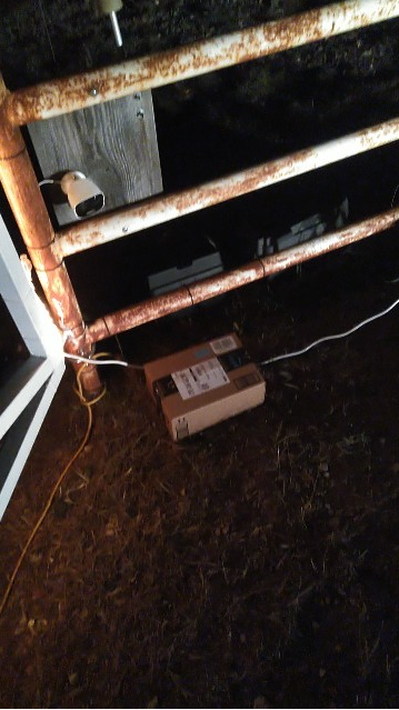
I have left the gate camera battery alone, other than monitoring it, for 10 days. Love the Shelly. More on that someday. Anyway, 11 days, technically. Today isn’t over, but 10 nights for sure.
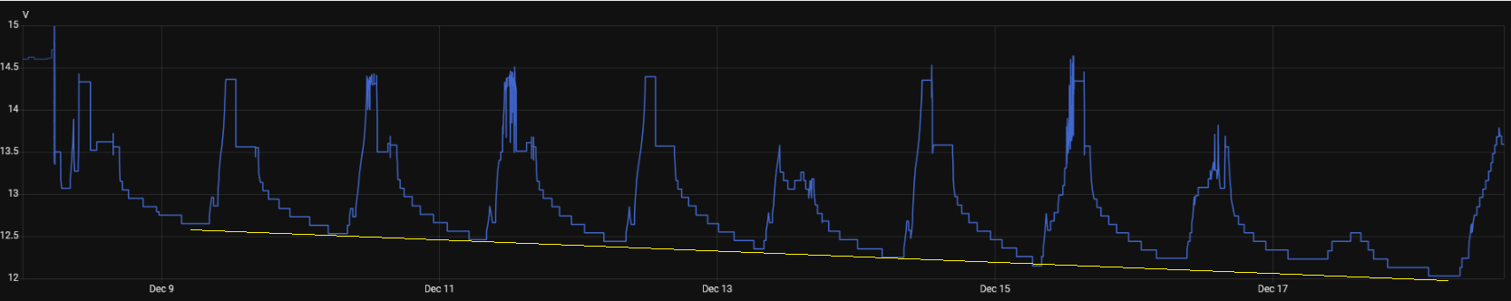
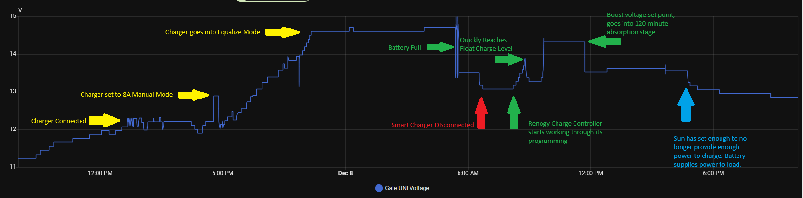
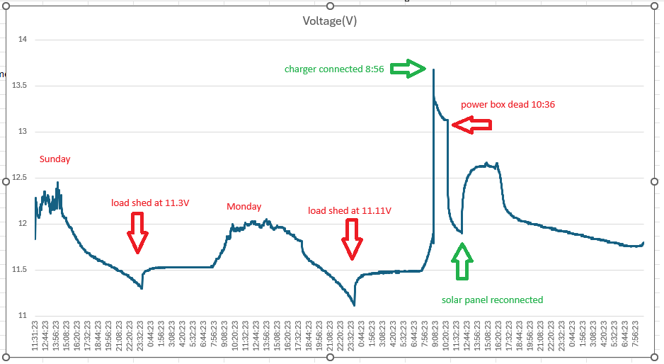
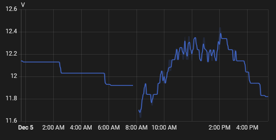
You may need to click on that image to see the detail, but there is a pretty much linear decline in the “peak” nightly discharge. Overnight December 9-10, it discharged to 12.65 volts before a sunny day recharged it to 13.5 volts. Every night, it would discharge a little lower, then a sunny day would bring it back to 13.5 volts. December 13 was cloudy for much of the day, so we didn’t get a 13.5 volt peak, but the 14th and 15th were sunny enough. The 17th was dreary and today, the 18th has been sunny thus far.
However, each night, the battery discharges a little lower. 12.65 volts the first night, then 12.53, then 12.46. Each night lower until last night, 12.03 volts.
Here’s the rub. I don’t know if this is just a normal decline after the sorta mega charge from the AC powered smart charger and it’s just slowly settling back after that, or if it’s a symptom of a problem and I just happen to have a big enough battery to help make it take a long time to show up.
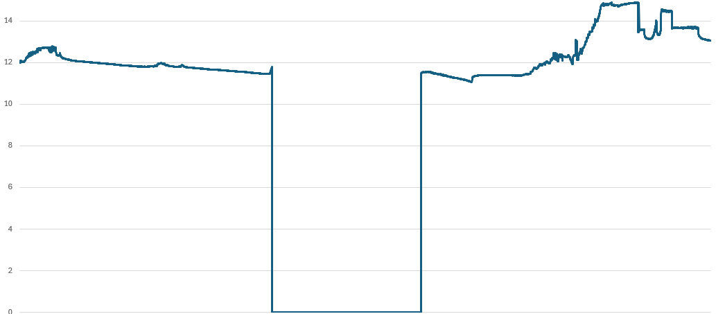
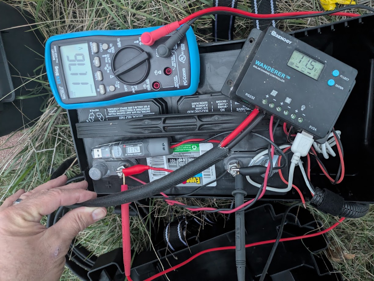
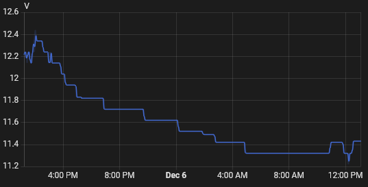
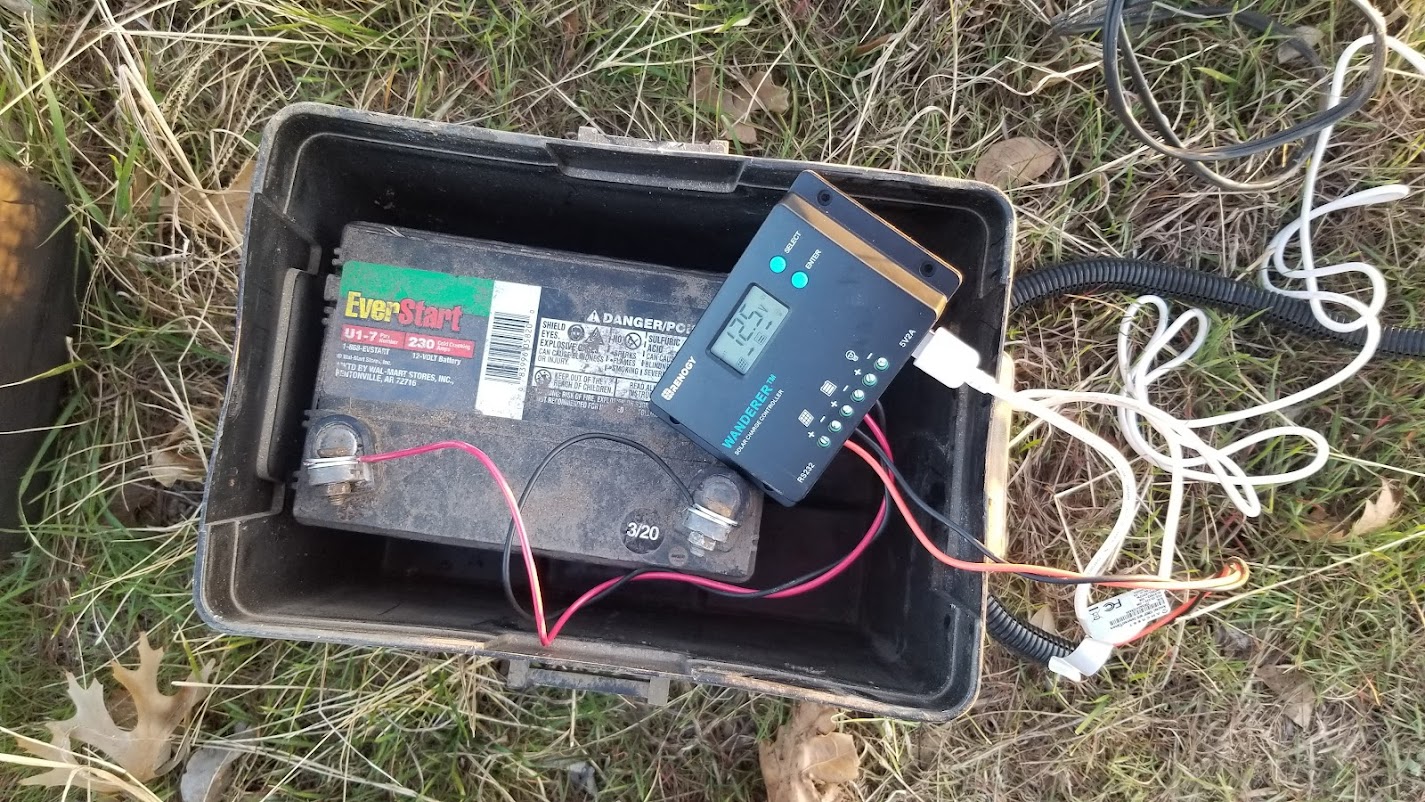
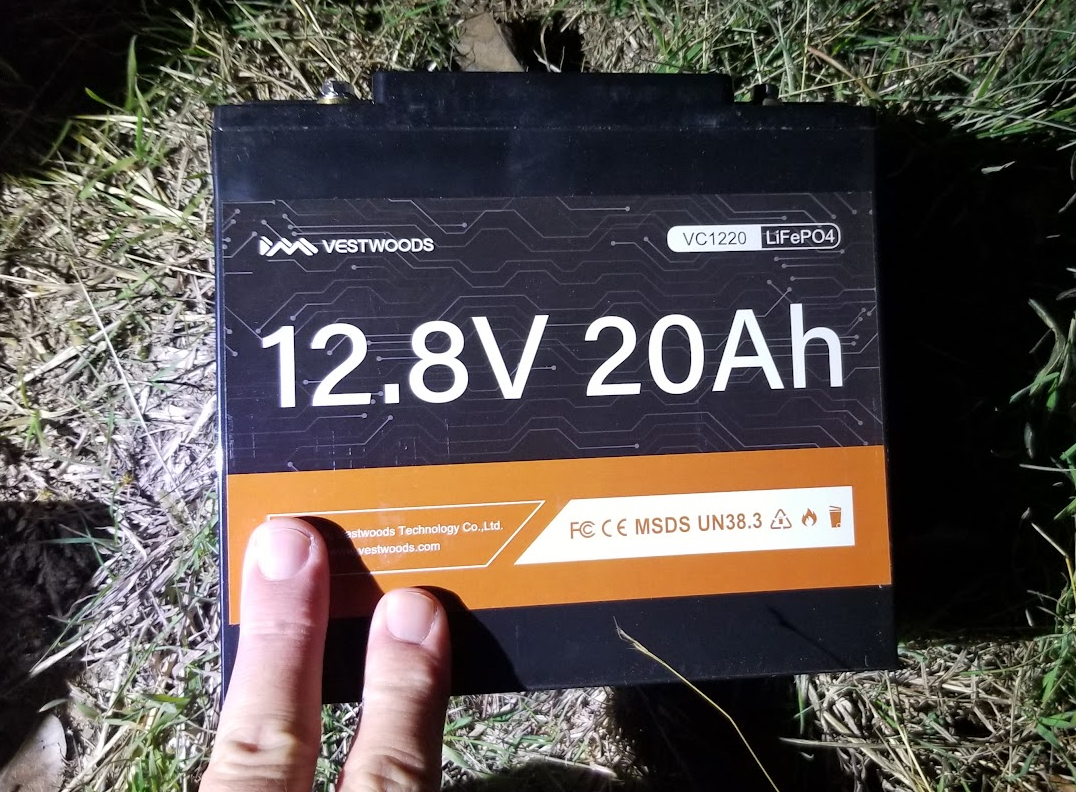
I do have an apples to pears example to compare with. I put the Triplett logger on the gate opener battery for week or so.
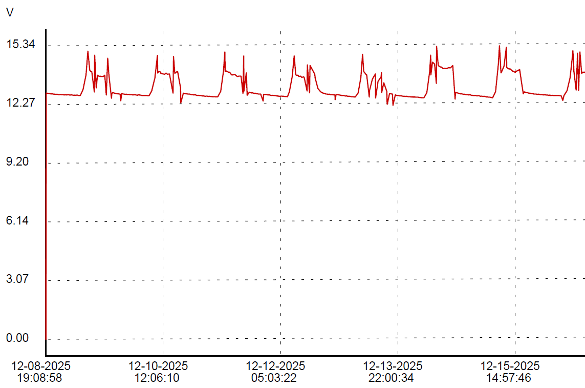
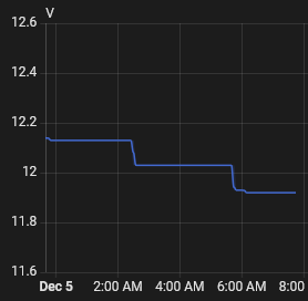
First, I love the sharp little peaks that (probably) show gate usage. If I get ambitious before this gets posted, you’ll never see this sentence, and will instead see my evidence that the little jabs in the opener chart correspond with gate operations. Or maybe because I just like this paragraph I’ll leave it anyway. You’re not the boss of me!
See, I told ya.
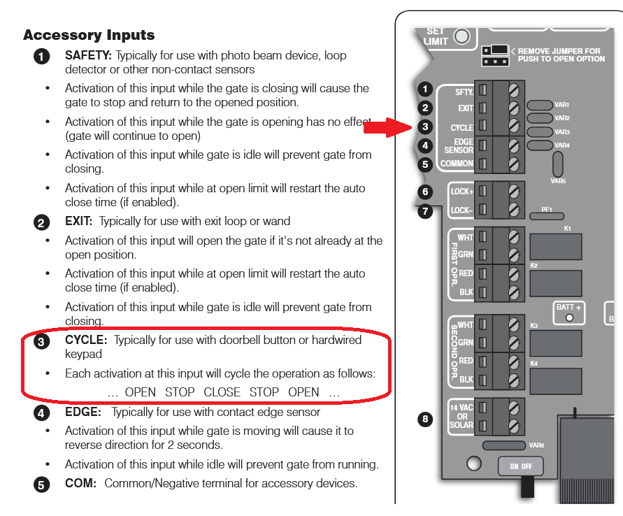
Dec 16 gate activity:
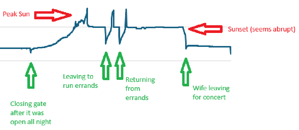
I am not sure what causes the positive spikes. There is nothing obvious in the gate camera at those times.
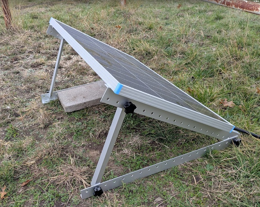
The two battery deployments are exactly the same thing except that the gate opener has an unknown but likely minimal charge control built in instead of a purpose designed solar charger controller, it has a small lawn tractor battery instead of a large deep cycle battery, it’s only a 10 watt solar panel instead of a 100 watt panel and the load is almost nothing most of the time instead of a camera, a WiFi AP and a Shelly UNI running 24/7. Both batteries are black plastic, made by the lowest bidder, so there’s that…
Since the data from both logging sources are available in CSV format, I thought I would try to match up the charts in a spreadsheet, but there are significant enough differences between the data sets, due mostly to the delta method employed by the Shelly UNI, that it is not trivial to match them up. The Triplett has even time between samples, the Shelly samples only when a significant enough change occurs. I am certain I *can* match up the data, but I’m not sure it’s worth the effort.
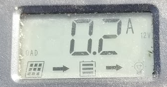
Even so, one can kinda look at the data and, even if I can’t easily share a spiffy visualization, I can report that the opener battery bottoms out at 12.67 volts consistently, give or take a couple of 100ths, each night in the logged data, unlike the big battery with the big panel, that seems to progressively lose ground every night.
Then again, maybe 10 nights isn’t enough to know the bottom of the pattern yet.
And who knows what spring and summer, with the sun higher in the sky will bring.
Too many variables.