I didn’t have much time to work on Buzz over the weekend, but the time I had was at least visually exciting.
I hand fitted the intake flanges I made, which basically means that I made the mounting holes more like mounting ovals. It didn’t take much metal removal for them to fit. I don’t know if it will matter long term, but I stamped each one to match the cylinder I fitted it to. Likewise with the gaskets I cut for each, although the gaskets are much more forgiving. After cutting the gaskets, I applied a bit of high temp black silicone gasket compound (some Permatex product, forget the exact one. In reading the label, it looked like the right thing to use) and bolted them on. The stock bolts were too long since my intake flanges are markedly thinner than the stock part. I got new M6x16 socket head bolts with washers. I did not have the torque specs at hand, nor do I currently have the appropriate range torque wrench (assuming the torque spec is not in the tens of foot pounds) so I made them snug, but not tight, pending the application of the proper tool. Actually, now that I think about it, the factory torque spec is for a plastic and rubber part and is not really likely to apply to my metal part. Best guess, then. Tight enough to seal and tolerate vibration, but not enough to distort all the parts and strip the heads ![]()
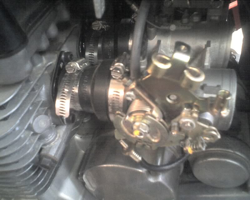
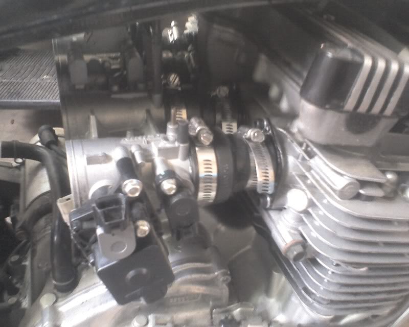
With the intake flanges in place, I HAD to put the throttle bodies on, if only to photograph them. Sorry for the shaky cellphone picture. I took it at lunchtime today after wrestling with the good (perhaps only formerly good) camera for long enough to be late back to work.
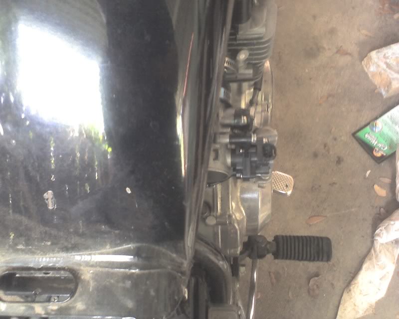
I took pictures from both sides and from above.
You can see here that my fears about the throttle body assembly being too wide for the bike may not be unfounded. On the left, there is more room, but the stuff sticking out is moving stuff, namely the throttle pulley. Maybe worse is that the throttle cable will need to take a sharp 90 to tuck back under the tank.
I did not have time to put the seat on and sit to see exactly where these parts land, but I’m betting they are right next to the knees because that would be the least desirable place for them to happen to land. ![]()
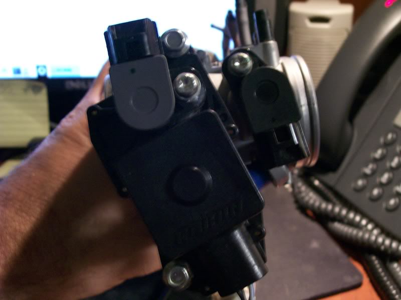
On the right, it’s at least a stationary part. The larger piece more visible here is the stepper motor and position sensor for the subthrottles. I really wanted to leave them in place in the hopes that someone more brilliant than I is working on MegaSquirt code to support them. Afterall, Keihin and Kawasaki thought they would be handy. In any case, shoehorning the throttle body into my bike is arguably more important than keeping a feature I can’t support, so they may go.
While I’m removing the subthrottles, I’m going to see if I can move the pulley to the center of the assembly. This could possibly let me keep the existing throttle cable as well as clearing the moving parts off the lefthand side. The tricky bit of that process is that the left and right halves of the throttle body have an adjustable synchronizing link in the center. Not only is this link located where I would need to put the pulley, but the stock synchronizing procedure involves adjusting this link. Theoretically, I should be able to solidly connect the two and synchronize all four TBs with only pilot air screws. It may actually be simpler that way. The synch adjuster between the two halves may actually add a step to the synch process. Shrug. I’ll just have to look at it and see what I can do.


