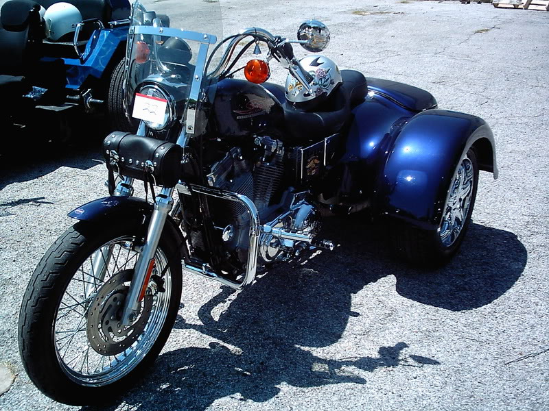
Sick Day Two


Even though I’m still pretty much in recovery from this cold thing, I went to work today. When I got in, I still felt good enough to work on intakes that never end. Except they did, they are finished. I filled in the gap on the flat sides with brazing rod then ground on one till it was too hot to comfortably hold, set it on the anvil to cool and ground on another. Cycling through them all in this manner, I got them flat within my desired specs then polished with emery cloth and a coat of paint on the surface that will be visible when they are installed. I still need gasket material and since my flange is quite a bit thinner than stock, I’ll end up needing shorter bolts than the stock 20mm long ones. Might was well make them stainless steel while I’m at it. :)

The EMachineShop software let me print out the wheel to scale. I cut it out and made sure it would fit. I also verified, very non-scientifically, that the existing sensors are indeed variable reluctance sensors, which greatly increases the chances that I should be able to use them with the EDIS module.

I think I may make at least one attempt to make a 36-1 trigger wheel before I order one. The signal is primarily used for clocking, firing a spark once every 17 or 18 pulses, accounting for the missing tooth, so I think that so long as the teeth are reasonably well spaced, the performance will not suffer. I’m more concerned with making it dynamically balanced for the 9000+ RPM redline.

What I have in mind is cutting a 3.2″ disk, rounded up in the drill press. Then glue the printout to the surface to use as a drilling and cutting guide, drilling the base of the teeth and using a jewelers saw and files to profile the them. Can’t hurt, right?

Otherwise, I don’t have an official checklist of things left to do, so I think I’d better start one…

Test fuel pump and regulator wet, note current draw.
Install fuel return in fuel tank.
Cut and install plate for mounting hardware.
Install the throttle body and fabricate mounting bracket.
Extend/replace throttle cable.
Weatherproof *or* repackage MegaSquirt.
Find suitable mounting locations for CLT and IAT sensor.
Devise suitable crankcase ventilation with airbox gone.
Find and acquire Ford coilpack and plug wires
Find and acquire a IAC solenoid. It could possibly operate the idle cam on the TB
O2 sensor (I’ve pretty much decided to forego it until I can get a wideband)

I’m sure there are plenty other bullet items and none of these include all the little stuff required for each item :)

Sick day


I was home today, sick with some sort of a cold. Late this afternoon, around 5PM, I felt like sitting up at the computer for a while and installed software from eMachineShop. I have to muck about in Windows running it, but the software itself is pretty well done.

EMachineShop is CAD software. You are limited pretty much by your imagination, but you can design any piece you need, in just about any material, made with just about any processes. The software analyzes your part(s) and gives you a quote, including shipping, for the parts. Obviously, the more complex (or exotic) the machining process and/or materials, the higher the cost. When you’re happy with it, click “Order” and your design goes to them and in a few weeks (21-25 days for my design) you get your parts at your door.

For my part, I need a 36-1 ignition trigger wheel. There are 4″ wheels available, but the maximum size to fit in my space is 3.2″.

It took a little bit to get the hang of the software. I needed an “array” command like AutoCAD, but I could not find one. It may be there under a different name. In any case, I drew a 3.2″ circle, a 3″ circle and a 2.8″ circle. Then I drew lines from the center of the circle to a point outside the 3.2″ circle, specifying the line’s angle in 5 degree increments. Using the intersection tool, I broke each of these elements into segments where they intersected and basically erased any line that wasn’t a 36-1 wheel. :) I have removed extra material opposite the missing tooth to keep the wheel balanced. As calculated, this deeper slot should actually be a teeny bit shy of balancing the wheel, meaning I can use a file to remove more material to balance it manually, plus it’s not really diametrically opposed to the missing tooth. Perhaps by the time I’m ready to order the work, I will remove two smaller notches on either side of the opposite tooth. [ed note: Later when the stock ignition rotor was removed, I noted that it’s hardly balanced at all. The two punched holes would probably need to be doubled to even come close to balance. Consequently, I think I worried too much about balance, but *my* trigger wheel is very close to balanced!]

The software lets you play around with which machines and materials to use. I need something ferrous for the sensor to work. Plasma cutting and laser cutting looked the most likely and laser turned out a little cheaper when cutting more than one.

1 laser cut wheel is $197, but 2 is $192 and 3 is $192.82. The price each keeps dropping as you add more units. For example, 10 units are $225, only $28 more than only 1.

Intake Fab, Cont.

It took a couple of days to do a good job of it, but I have the intakes nearly finished.

I rough cut the flanges one at a time with a sabre saw, then clamped them together and ground them to shape as a unit. I marked and drilled one plate, then clamped them together again to drill the mounting holes and a pilot hole for the center. I hole-sawed each center hole separately.

I was rolling along so well that I forgot to photograph the pipe cutting and brazing. The “before brazing” photos are actually of the prototype, which you may notice has the pipe off center and does not have the taper referred to next. Anyway, for the pipe, I had already cut a threaded end off, so I slightly tapered that end of the pipe and wire brushed the factory coating off. I used a standard plumbing-type pipe cutter and cut a segment about 1.2 inches long. This makes a rough and slightly distorted end, but it’s square to the end of the pipe. I cleaned up the cut edge on the grinder and set it aside.

I clamped the first flange and used a deburring tool to slowly increase the diameter of the center hole until it made an interference fit over the tapered end of the pipe segment. The flange was gently hammered all the way down to the non-tapered end of the pipe segment, making it as flush as possible to the end of the pipe.

I then put the assembly on a brick (I recommend a real fire brick for this; my brick will someday pop off shards of hot brick that will land either in my eye or on Toni’s trike. I think I’d prefer it land in my eye, for that would probably hurt me less.) and brazed the seam.

If you haven’t done brazing, it’s really just a solder that melts at red hot. It’s about as easy (to me, anyway) as electronic or even plumbing soldering and I find it much more forgiving to the novice than welding and is often more appropriate anyway. The joint almost always stronger than the materials being joined and the relatively low temperatures are less likely to alter the physical properties of the materials. It’s not appropriate for joining really big pieces, but it is good for joining dissimilar metals, like copper to steel, etc. Welding copper to steel is very difficult because copper melts away before steel reaches welding temperature. Enough about that…

My prototype intake was seriously flawed in two ways. Earlier I mentioned that the center hole was not indeed centered. It could theoretically affect the flow of fuel-air mixture, but the net effect would probably be pretty minimal anyway because we’re going from the throttle body into a short rubber reducer, the small end of which is clamped to the intake. The turbulence from a 1/16″ offset would probably not be noticed with all the other obstacles!

The other flaw on the prototype is that I attempted to use a standard air-MAPP torch for the brazing. It does get it hot enough, just barely, so it made a good seal and a mechanically sound joint, but it was lumpy. I think I could have suspended it on wire or some such and heated it uniformly enough with that torch to reflow the joint, but I was going to replace the unit it anyway. This time, I used a MAPP-oxygen torch, which gets way hotter. The result is that the piece heats up faster, flows the filler better and does it fast and efficiently enough that the brick isn’t heated all the way through in the process.

Then I did three more just like it.

The only flaw in the new ones is that the mounting holes ended up ever so slightly too close together, but at least all four are the same! I will slot them a bit and that should be that. What’s left is to surface grind/file/sand the flange face that mates with the engine, apply some black engine paint to hide my beautiful brazing and find gasket material to cut for them and they are ready to bolt on.

Intake fab

I am going to fabricate intake flanges, hopefully tonight. I picked up most of the hardware I will need at lunch today, namely some 2″ wide bar (I got 1/8″ thick, though I was hoping on 1/4″) and some 1″ pipe.

Each flange is basically going to be an appropriately shaped base, with mounting holes drilled in the wings and a large hole in the center. I will cut a short piece of the pipe, fit it to the hole and braze it in place. After grinding/filing/brushing them to finish, I will cut gaskets to fit and bolt them to the engine intakes.

I found neoprene plumbing reducers of a suitable size to interface between the intake flanges and the throttle bodies. They are only $4 each, as opposed to $12-$20 each for silicone. Assuming it all works, I will probably replace them with spiffy pretty silicone ones later, but these should do fine for getting Buzz running again. In either case, the rubbery reducers should allow enough flex to account for the spacing differences between the intake tracts and the throttle bodies.

I salvaged my fuel pump from an in-tank unit purchased on eBay. The in-tank design has pump, pressure regulator and surge tank (as well as fuel level sensing) in one simple unit, but the whole unit could never fit in the Maxim’s tank. I will have to plumb these pieces together externally. At this point, I have all the tubing I need for hooking up the fuel pump, but I’m short a T to connect the regulator. The regulator basically relieves overpressure by bypassing the excess back to the tank. I need to feed the output of the pump to the T, then connect one side to the throttle body and the other to the regulator. The regulator’s bypass port will be sent back to the tank, which will require adding a return path. I think I can use a weldless bung for that connection. If not, I will need to make the tank safe for brazing heat. This can be done by rinsing it with soapy water and once I’m ready to do that, I may as well apply some tank liner, too.

It looks like I will have to fabricate a trigger wheel for my EDIS ignition. There is a company in Britain that sells laser cut ones that would probably fit, but it gets expensive fast. Surely, there is a domestic manufacturer of such things? For a motorcycle, it needs to be a small unit, probably no more than 3″ or so. The smallest from DIYAutotune is 4″. Maybe I need to cut a deal with eMachineShop.

I need to stop for the T and some brazing rod on the way home tonight. I will also get a fire extinguisher or two, for beginning probably this weekend, I will be working with liquid fuel under pressure.

Buzz comes apart!

Well, after a month and a half without working on it, I finally actually started taking Buzz apart for the EFI project…

I took a bunch of pictures that are kind of intended as documentation for reassembly, but some are more interesting.

I knew the bike was far from spotless, but digging into the depths reveals how dirty it really is. Yucky. Flash photography also reveals much grime that my eyes seem to overlook.

The fitting of the throttle bodies to the engine is the biggest question mark at this point. Of large concern is the width of the throttle body assembly. In a quick eyeballing, it looks like the stepper motor for the subthrottles, something I had intended to leave intact for future expansion, may stick out far enough to hit the rider’s right leg. Also, the throttle cable connects to one end of the TB but connects to the center in the stock rack. At the very least, I’ll probably need a longer cable. I may also be able to install it “upside down” to put the throttle on the other end where it may reach better. I also don’t care too much for the single cable arrangement depending on a spring return, though I have not personally ever had one stick open on me.

As for connecting the TB to the engine, the photos will reveal a substantial difference in the carburetor throats, or at least where they have to connect.

I have found silicone reducers in appropriate sizes, ranging from $12 to $22, usually in blue, but sometimes in black, red or other colors. Purple intakes, anyone? Anyway, using a reducer and custom fabricated intake flanges, I think I’ll have the TB mounted very soon.

I have done minimal testing of the fuel pump. It runs and running dry, it pulls a little more than 1A. I really expect that to climb substantially once it’s pushing fluid under working pressure. I hope to test that tonight, for the power budget is still the most likely reason for the project to go south and the fuel pump is the power hog.

I had originally thought I would leave the stock ignition system in place, and I probably still could, but I have picked up an EDIS-4 module for which I need only the ignition coil(s) to complete. I am about 94.7% sure that a 4 tower coil for the EDIS module will fit where the stock coils are, perhaps with room to spare. The biggest questions here are whether the stock VR sensor will pick up my trigger wheel and of course whether a 4″ COTS trigger wheel will fit or if I will have to fabricate one.

I hope to be mounting the controller and most of the components in the space where the airbox was. One problem to solve will be replacing the sidecover mounting studs that were on the airbox. All 4 of them are pretty close to a frame piece, so I think I’ll be able to come up with something for them.

Well, if I get some answers tonight, I will let you know!