Category Archives: Flying Dog Forge

A Path Blocked

Ok, last path metaphor, I promise.

Plus, while it was extremely maddening while it was happening, it was actually resolved pretty quickly and could have been resolved three different ways. Really, other than its temporary effect, I probably shouldn’t say anything.

Before all that happened, I had been slowly resolving little issues bit by bit.

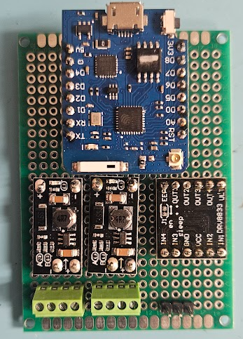
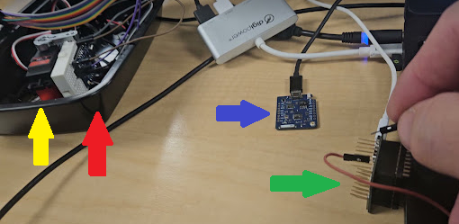
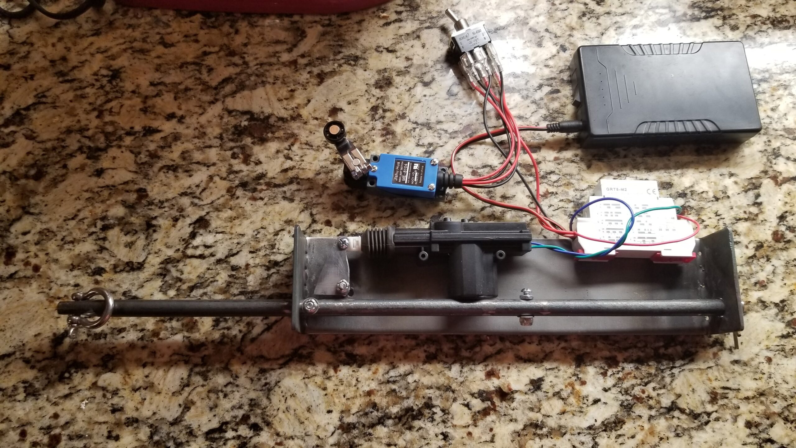
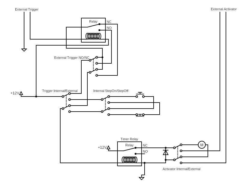
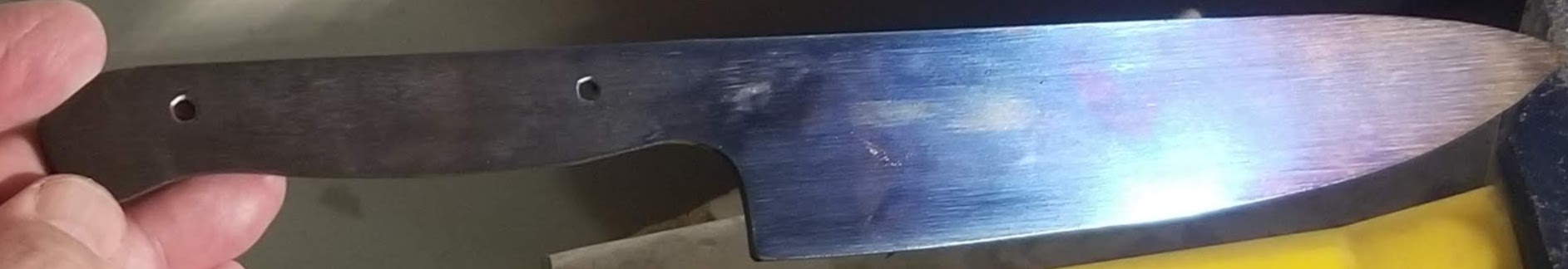
I have assembled what might be V1.0 of the Activator hardware board. The Trigger hardware board will probably be very similar, if not identical. Really, identical board with different software could be ideal.

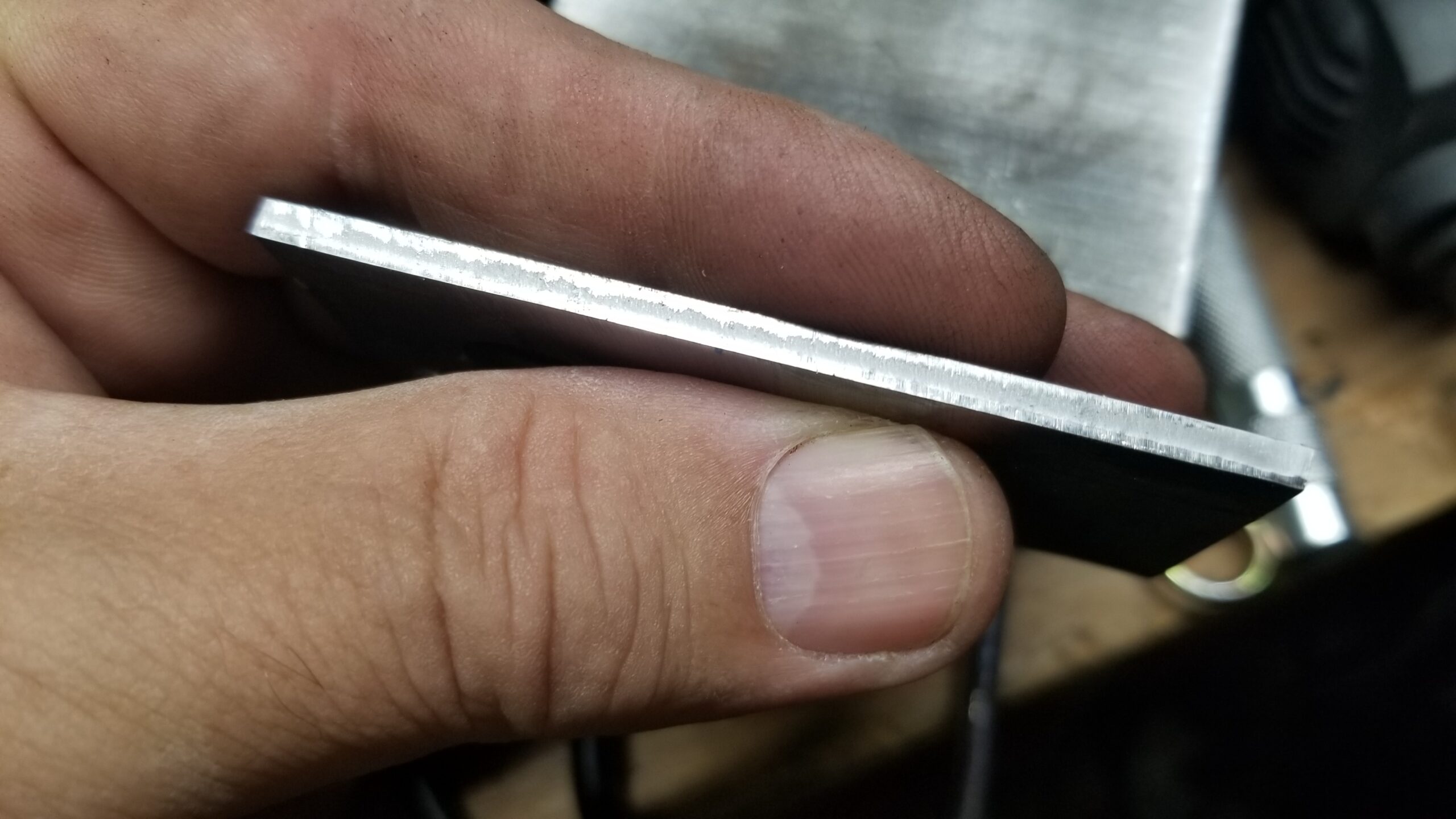
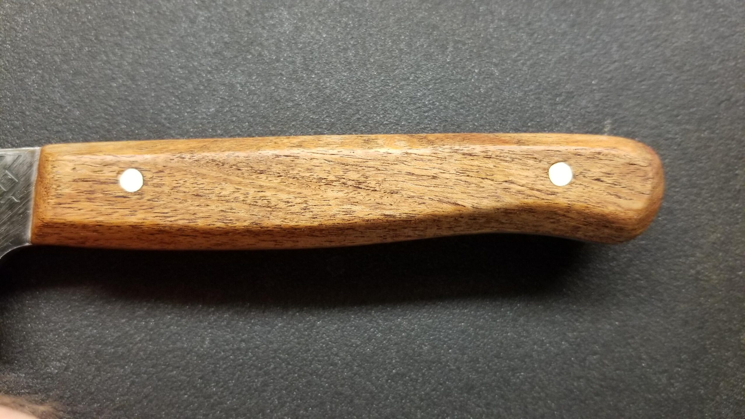
I say might because I find that I do not care for these particular green terminal strips. When I ordered them, I was expecting larger units. There is not a good sense of scale here, but these are eyeglasses sized screws. Actually, you can see that the screws are about the same size as the solder pads on the circuit board, which are about 0.075″ in diameter. I have already cross threaded one by opening it too far.

Otherwise, from left the right, the first terminal strip is for the battery negative and positive and the external power switch. The next strip is for the plunger reset warning light and the plunger sensor switch. The three pin header is for the servo that trips the plunger.

Above the connectors, left to right are the 5 volt regulator to run the controller, the 12 volt regulator to run the warning light and possible future things and a dual H-bridge board that currently drives just the warning light.

Finally, above that is the star of the show, a clone of the unbiquitous Wemos D1 Mini Pro, so called Pro because it has an external antenna connector, which will be handy since this board will be inside a steel box.

I had two power mishaps with this board. Really, it was one power mishap that caused two problems.

When I was researching what equipment to shoehorn into this system to implement wireless, I had some realizations that could be visualized like rungs on a ladder. First, I knew that my controller board was necessarily going to have to take up some space and my Activator device is pretty crowded inside already.

One step up on the ladder.

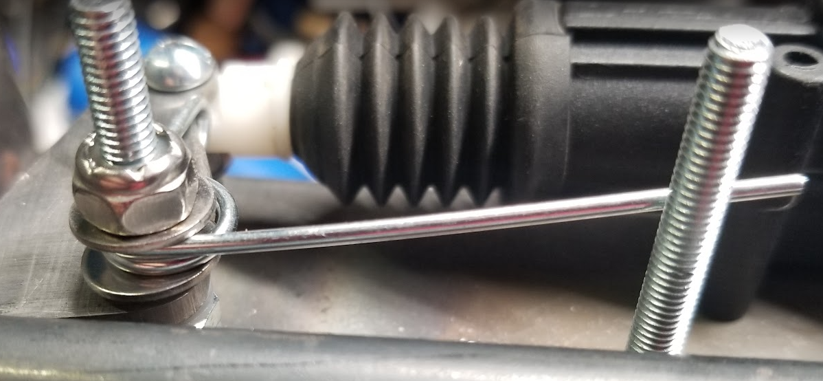
The industrial relay that protects the lock motor, while a very robust device, is at it’s heart a very simple device that takes to continuous power from outside and limits it to a short half second or so pulse to the lock motor. I will be providing that lock motor power locally now, through my controller board, which is smart and can do the time limit function. The industrial relay is also pretty big, so removing it might be enough for both my controller and the battery.

Next step up on the ladder.

The lock motor runs on 12 volts. I did some measurments and found that during it’s brief moment of activation, it pulls about 4 amps. If I limit it to less than about 3 amps, it doesn’t pull hard enough to reliably trip the plunger. That is not a terrible amount of current, but as I look around for commerical off the shelf 12V 4A lithium batteries with easy connections and easy charging solutions, they all tend to be kinda big. Way bigger than the space vacated by the timer relay, leaving no space for the controller board. Batteries of other chemistries are even bigger and don’t work as well, so I didn’t even look.

DC to DC boost converters are thing these days. Actually, I have had a really successful history with multivoltage DC to DC converters back in my robotics days. Unfortunately, those blogs were lost ages ago. Anyway, I shop for converters and in a field absolutely flooded with converters for 12 volts INPUT, the few that I could find with 12V output tended to be physically large multivoltage output units for 48V+ input or if they are boost converters that work at smaller inputs, they are never more than 1A out. There are a few exceptions in the $50 range and I really want to avoid those if I can.

I did play with the *voltage* on the car lock and found that, so long as it had plenty of current available, it would reliably work all the way down to just under 6 volts. 7.4 volt LiPO batteries are common and RC car batteries have commonly available connectors and chargers. I found some reasonably high Ah rated batteries and a nice charger that wasn’t stupid expensive and got them on the way, along with some appropriate connectors.

Next step up on the ladder.

Next, I knew I needed to power the controller. I have a couple of options. I can power it from the USB jack with a converter connected to the battery, but it seems more elegant and controllable to supply 5 volts to it externally. I have batteries coming and I did find some nice 5V 1A DC-DC converters in my earlier shopping, so I found them again and ordered a handful. They came in a package of 10, very inexpensive.

Next step up on the ladder.

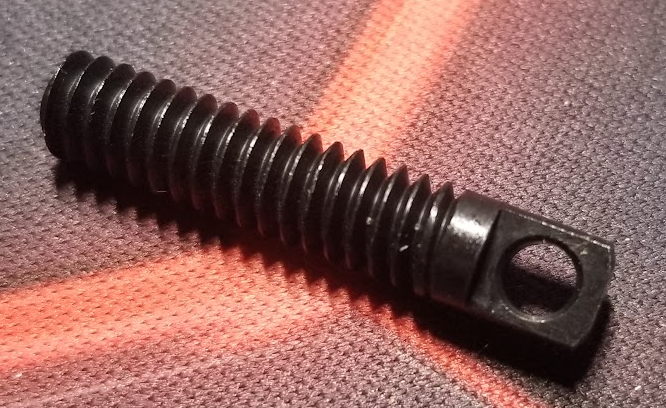
Big epiphany, with the controller board, I can directly operate a servo! This eliminates the need to ‘protect’ the lock motor and a servo is significantly smaller than the lock motor. I can power it directly from the board or even directly from the battery if the 5V 1A supply is not enough. That will also ensure I have more room for my RC car battery.

Next step up on the ladder.

I had tested the nice big warning light that I want to put on the Activator to remind people to reset it. At the time I chose this one, everything was running on 12 volts, so it made sense to get 12 volt lights. I got a variety of colors. I particularly expect to use red for the Activator light and red, yellow and green on the Control Box. Experimentally, I connected a red light to 7.4 volts from my bench power supply. It lights up, but not very brightly. It will almost certainly be hard to see outside even at full brightness. I need 12 volts for at least the light. Luckily, the same DC-DC converters I ordered above are actually adjustable for 5, 8, 9 or 12 volts output, so other than having to add it to the board, problem solved.

Next step up on the ladder.

This week, I had some time to tinker and got the board built and populated. I don’t think I connected power to it before verifying the power, but more on that in a minute. With the controller board out, I connected one of my batteries and found that the 5V board was outputting 7.9 volts. The 12V board was good, but 7.9V is not 5V.

The default tiny zero ohm resistor jumper settings on the boards is for 12V, so for the 5 volt board, I just removed both of them. I looked carefully to ensure there was not a solder bridge. I alternately shorted them to ensure they they indeed changed the voltage. Only with both shorted did they provide the proper 12V output. All three other settings were higher than they were supposed to be.

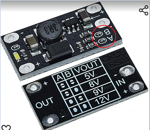
While I was looking up this chart to verify that I did indeed have the jumpers correct, I noticed the error of my ways. This little board is designed for 3.7 volt input.

At some point I briefly looked at 3.7 volt batteries and I’m sure these converter boards ended up in my search history at that point. Later when I just wanted converter boards, I remembered them but I was too high up the ladder to see the the voltage πŸ™‚

As luck would have it, 3.7 volts works fine for me, other than the expense of having purchased some 7.4 volt batteries that I don’t technically need, at least not for this part of the project. My charger will work for them, too.

However, I might choose better DC-DC boards.

I mentioned that these are inexpensive boards. $10 for a 10 pack. The voltage selection chart silkscreen on the actual board is completely illegible. All four setting for A & B look identically blotchy. And for what it’s worth, the output power pins are spaced 0.4″ apart, but the input power pins look at a glance like they are 0.2″ apart, but they are not. They fall somewhere between 0.2 and 0.3″. The output seems to be good for about 6 watts. The specs are somewhat iffy, but hints that higher voltages are probably at less than the 1A specified for 5V. The examples they give all work out to slightly more than 5 watts. This is fine for my needs. I don’t expect to need more than 150mA for 12V.

Until I put Activator board together, I’d been running this controller on either a laptop USB or a USB power pack. Now that I had it put on the board and running on my bench supply standing in for the 3.7 volt batteries that were enroute, it was nice to leave it on the kitchen table where it was close enough to hear the servo cycle, but but off my desk which was cluttered enough with the Trigger and ControlBox modules so that I could hit the buttons on them and observe the display on the ControlBox. For some reason, I had to interact with the Activator. I don’t remember why. While I was near it, I smelled that classic ‘something is hot’ smell. Since I had thrown over voltages at it earler, I finger probed and discovered that the inductor on the 5V board was pretty hot to the touch. I immediately shut off the power supply. I pulled to control board off, turned on the power supply and noted that the voltage was indeed 5 volts, so that’s good.

I presumed that the little 1A supply was having trouble keeping the controller and the servo both supplied, so I rewired the servo to run directly off the battery. That is a little below spec for it; it is rated for 4.8 to 8.4 volts, but in testing, it worked fine and still pulls plenty strong. I do not expect it to be a limitation for the Activator sear. Of course for the testing, the controller was plugged back in and in just a little bit, I smelled ‘hot’ again. I probed the power boards again and while it was not as hot, the 5 volt board was definitely getting warm. I probed around on the controller and ZOWIE a chip on the board was hot enough to immediately cause pain. I removed power again and pulled the board out. It turns out to be the USB serial chip. Once it cooled off, I plugged it into a USB cable on my laptop and it got seriously hot in a couple of seconds, so it definitely has a problem.

As mentioned earlier, I don’t think I connected the 7.4 volt battery to the system with the controller in place, thus applying basically 8 volts to its 5 volt input, but I can’t authoritatively say never. Plus, after working for weeks under various conditions, it acted up the day it was running on the new carrier board. The CPU seemed to be working, by the way. The USB chip was smokin’ hot, but even before I discovered it was baking, the device was responding to ESP-NOW messages and operating the servo. I’m just not sure it would have lasted much longer.

Happily, I have one not in current use, so I could swap it out. It is a slight pain to update the MAC addresses in the software to use the new device, but at least this one doesn’t sterilize the air around it. As these are my favorite boards for this application, small cheap boards with the external antenna connector and not a lot of unecessary IO, I may need to order a few more of them. I do have some 40 pin ESP32s with external antenna connectors, so I’m not without a way forward if needed.

In other hardware news, I have been using a slick device with a built in screen for the ControlBox unit. I don’t know if this will be the final controller for the ControlBox, but it has it’s advantages.

It is an M5Stack Core. I originally got this for ESPHome use and HomeAssistant, only to find that it was not yet supported there. I have not rechecked lately. Anyway, it is an ESP32 in a nice case with a few built in goodies, most importantly for this, a 320×240 TFT display and three front mounted buttons. It also has a speaker, a TFCard slot and, while I’m not sure how long it can run on this, it has a 110mAh battery built in. I am thinking about building a little program to send a message to another module once a minute, with the other module logging the time and see how long it lives.

For use as a real ControlBox controller, it has one drawback. There is not a really strong way to secure external connections to it. It has a row of exposed pins on one side and exposed pin jacks on three sides. The pins are not ideal ones for reuse for my purposes and the pin jacks would be even more difficult to really secure the connectors to for a device that might get tripped over or dropped and has to travel on gravel roads in someone’s trunk or pickup bed. In the long run, I may need to use some descreet components for these setup.

But for now, it seems a good way to start, with a caveat.

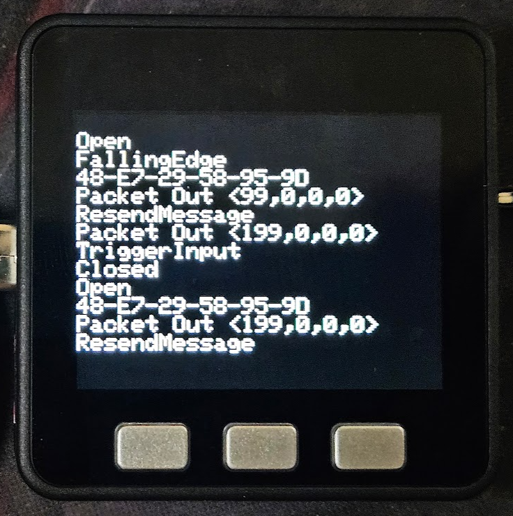
This was before I had it doing anything with text fields. I was sending stuff I would normally dump to Serial0 to the TFT instead.

I have found that, like many of these small hardware displays, or at least the libraries written for them, you often can’t just throw text at it and have it behave the way you would like it to, like scroll like a classic screen. On the screen as shown above, I can send one more line to it, then any subsequent lines will just continue to clobber that bottom line, text written on top of existing text.

Visuino supports text fields. The field is located anywhere on the screen by x-y pixel coordinates then prints text you provide with the font, size and color attributes your provide. But so far as I can find, there is no clear command. Subsequent text clobbers what’s already there. Argh.

I had been working on this issue reiteratively in what spare time I have for a few days now. I have a nice title bar and I intend to determine and display the status of the two (currently) available remote devices and provide a 3-4 line messages window of scrolling messages about whats going on, trigger received, trigger sent, test sent, device needs reset, etc. I have a label over one of buttons at the bottom of the screen and if you push that button, it sends a test trigger to the activator. All of these things work, until you put enough text somewhere to clobber what’s already there.

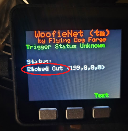
The only way I have found to clear the screen is to literally clear the entire screen, write it black, then rewrite all this stuff back to it. That seems completely ridiculous and it puts it on me to maintain a screen map somewhere. That’s not what I want to do. I want to make my hardware do stuff and print stuff on the screen to tell my users what my hardware is doing for them. The IDE should know how to make the *display* do stuff.

Sparse documentation is a recurring theme here. For example, these are two very similarly named components:

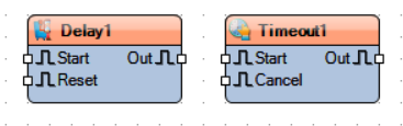
If you get context sensitive help for Delay, you get a Wiki page with thin but not entirely useless descriptions of the settings for the component and what the Start, Out and Reset pins do, as well as links to some example projects that happen use it.

Maybe Delay doesn’t do exactly what you are looking for. Logically, it seems like Timeout might do a similar kind of thing but attempt to get context sensitive help for Timeout and you just get:

It offers that you can search for it in other places, but so far, that has universally not helped on anything I have searched for. I suppose it could happen. Maybe I haven’t looked for the right thing yet.

Which brings me indirectly to my brief but severe irritation last night.

Regardless of this irritation with the documentation, I like the product. I was able to reach a working point with my devices very quickly. As always seems to be the case, a lot more time goes into the user interface than to the actual device (especially if you can’t figure out how it works). Anyway, I had been running on a 15 day trial version of Visuino Pro and there were two days left. I saw no reason to not proceed with the purchase. I looked at the version matrix and while I had been running the Pro on trial, I didn’t see anything in the Pro column that I was actually using, so I elected for the Standard version with a 1 year subscription for updates. The purchase, install and registration went through without a hitch. It automatically opened after installation and I pulled up the ControlBox project and played with it a bit. After a little while, I needed to open a second instance to make a companion change to the Trigger project. When did that, I noticed/remembered that I still had Visuino Pro installed and, fatally, decided to pull up control panel and remove it.

Long story short, had I removed Pro before installing the Standard version or reinstalled Standard after removing Pro, things would have been ok, but the removal of Pro removed all the components from the Visuino library folders. There was some minimal number of components that I guess are built in to the binaries and support for only the Arduino Uno R3, but my projects now spawned a huge list of errors, most of which were missing components and many of those were specific to my missing board. Once I had seethed down to being able to write without being overly abusive, I dashed off a note to Visuino support. I don’t remember exactly the details, but in short I wondered why the uninstall script would remove user files like all my components.

Interestingly, all of this was loaded on my work laptop, which heavily uses Microsoft OneDrive. Not long after my note to support was sent, OneDrive serendipitously popped up a dialog asking if I wanted to permanently delete the several thousand files I had deleted recently. I dove into that dialog and found that I could restore the folders that the Visuino uninstall script had deleted. I ran Visuino and everything was happy as it could be. I was was exhausted and shut everything down and went to bed!

By morning, I had a reply from Visuino support, patiently telling me that a reinstall would most likely fix it and that my own projects were safely stored elsewhere. I am certain that is true and I will probably do that because in restoring those folders, I am sure I now have some Visuino Pro components that I have technically not paid for. Then again, the program and/or license may be smart enough to prevent them from working. Shrug. As I noted when I looked through to version matrix, I wasn’t using any Pro components, which consisted mainly of FFTs and other such advanced data processing components. Interesting, but not applicable to anything I am likely to need for yanking on chains by novel means.

Where The Path Leads

I have made what I think is a lot of good progress with both Visuino and the hardware.

The Visuino sketch shown in the last post kind of worked regardless of being very wrong in a couple of places πŸ™‚

I had made a comment on a video about the recent massive expansion of Visuino. I noted how my code basically ran once when the first signal was received after power up, but since that same value gets sent repeatedly, the received message never changes and the code never seems to see subsequent received messages. None other than company founder Boian Mitov replied, asking for my program and details so he could offer suggestions. I excitedly sent a (far too wordy, as is my modus operandi) email and expectantly waited. Of course, I continued working on it and found a (naive) workaround that (kinda) worked, though it would come to light later that it was not actually responding to *the* command, but rather *any* command.

Several days later, the reply came from Mitov, with apologies for the delay, but with a beta update of the software that had several changes, including how the CompareValue component works. Between the guidance provided and my own experimentation in the mean time, I was definitely set upon the proper path and that piece of code was *truly* working!

My current design has three main devices, the Trigger, the Activator and the ControlBox between them. I have three ESP8266 devices, appropriately labeled Trigger, ControlBox and Activator. Trigger looks for a button press and upon detecting it, sends a message indicating that to its ESP-NOW peer, the ControlBox. At this point, ControlBox literally just retransmits the received message to its other peer, the Activator. Activator receives the message, verifies that the message matches the command to act and then cycles a servo, which will trigger the mechanical yanking device.

ControlBox will also have a dry contact input so that Trigger is not necessarily needed in all cases. Eventually, ControlBox will have a display and buttons driving a menu system where various behaviors and parameters can be selected.

At one glorious point, all three ESP8266 boards were scattered across my desk, communicating wirelessly at a range of 10’s of centimeters. It looks more chaotic than it really is.

image.png

The Trigger device is circled in green, the ControlBox in red and the Activator in blue.

As it currently works, pressing the button on the Trigger sends a message (an integer, 199) to the ControlBox. At this point, the control box retransmits the received message unmodified to the Activator. If the received integer at the Activator is 199, it cycles the servo, which will one day soon trigger the spring loaded device.

Future features will include a sense switch in the activator to warn people at the ControlBox that it has not yet been physically reset. Because of the way stages are reset between competitors, some triggering devices can inadvertently trigger a moving target before the stage reset is completed, so being able to arm/disarm the Activator from the ControlBox is a necessary feature. Since all these devices will be run on batteries, a battery status indication at the ControlBox will help ensure that all devices are ready to go. Finally, the ControlBox will be able to sequence multiple Activators. This is a rarely needed feature, but if my device can do this, it will sell πŸ™‚

The fun bits that I have learned along the way:

I need to accomodate either a normally open or normally closed input for the Trigger. The DigitalDemux component makes that pretty simple. The contact goes to the input of the demux. The select switch goes to a DigitalToInteger component to provide a selection for the demux. The outputs of the demux go to EdgeDetector components, one configured for rising edge and one configured for falling edge. The same logic will be duplicated for the electrical input of the ControlBox.

image.png

When I first implemented the ControlBox, I over complicated it. Out of hardware hacking habit, I tried to use the minimum number of bits possible. I had set up the Packet and Unpacket components to use 8 bit integers. This worked, but somewhere in the mix, an integer is a 32 bit value and wrestling with resolving that was becoming troublesome. I had a situation wherein the first byte of the full integer was being interpreted as the command byte and that first byte was *not* 199. Eventually, I realized that ESP-NOW sends a packet with a minimum of 36 bytes and whether I send a payload of 1 byte or 4 bytes makes about 10% difference in the entire message and dealing with a regular signed integer is simpler than trying to shoehorn my ancient bitbanger ways into the mix. Once I abandoned all the conversion necessary for 8 bit integers and literally connected the received output to the transmitter input, it just worked.

image.png

The Activator has been the problem child and was the original reason I posted the comment on the YouTube video. It needs to react to an ESP-NOW command message, but only the right command. Other commands might include a status request, a command to turn a light on or off or a command that sets an operational parameter. I can’t just assume any message is a command to activate. This is why I was struggling so with the the old CompareValue component. However, the new version works better and other advice from Mitov cleaned up everything else. The chain is very simple and straight forward now. The received message is tested to see if it is the activate command. If so, the EdgeDetect component converts that to a clock pulse, which activates the sequencer to cycle the servo.

image.png

I learned that the sequence works slightly differently than expected. The Analog Value is set immediately, then the sequence time elapses. I first presumed that this timer was started and ran, then at the *end* of the sequence, the AnalogValue would be asserted. Now that I realize the proper order, then of course that makes more sense than what I was thinking. However, before I figured that out, there was a noticeable delay between when the button was pressed and when the servo moved. With copious serial prints I was able to verify that the delay was not in the transmission or reception of the ESP-NOW message; that is essentially instantaneous. The delay came from my misinterpretation of the Sequence component. Originally, I was setting the servo to 0 for 10mS, then for 500mS setting it to 90 degrees, the setting it back to 0 for 500mS. The intent was to first ensure that the servo was in it’s home position, then move to 90 degrees, with the first 500mS to ensure it had time to move, then move back to 0 degrees, again with a 500mS time to ensure this had time to happen.

Wellllll…Β  turns out we don’t need most of that. The Servo component includes an initial value, which apparently homes the servo automatically at startup and then the timing of the sequences was not where I thought they were. The AnalogValue for moving the servo is asserted immediately, then 500mS later, the return to zero value is asserted. This is much simpler than I first presumed and makes for MUCH more elegant process.

If I were to make any complaint about Visuino, it would be that we need some kind of programming guide to demystify the inner workings of these components. The examples in the plethora of available videos often showΒ whatΒ to do to make a light blink or whatever, but rarely describes *why* a certain feature is used. For example, a demo on operating a servo had a DivideByValue between the selected AnalogValue and the Servo. Only after extensive experimenting did I figure out that this provides the appropriate fraction needed to scale the degree value requested to the range of PWM that the particular servo will respond to. In the absence of more precise guidance, one could easily assume that the Servo component scaled these degrees itself and would accept a degree value as input. Quite accidentally, “0” and “90” as direct inputs to my servo appeared to work properly, but it turned out to be not 90 degrees, but the full 270 degree range, viewed I would say “backwards”. 0 went to zero, but “90” was so far beyond the 0 to 1 range that it simply went to 270 degrees. As it is a digital servo capable of 360 degree rotation, it took the shortest path counter-clockwise to the requested position, as opposed to the long way, 270 degrees clockwise. Some documentation revealing that the servo requires a 0-1 range instead of a direct degree heading might have revealed this issue much earlier in the process.

As for the hardware, I began laying out prototype circuit boards for the system, starting with the Activator. This is how it turned out before I started wiring it up.

At the top is the ESP8266 board. In the middle are two boost regulator boards (more on that in a minute), a cheap motor driver board that will actually be used to drive the warning light, with room to drive a motor in the future. Along the bottom are connections for the battery, external power switch, sense switch for the punger and the light and finally, the header for servo to trip the sear.

With the power supply boards, I got a little too clever for my own good. They were spec’d out when I was contemplating 3.7V batteries. I don’t recall why I landed on 3.7 to start with, but I did. These boards take a 3.7V input and boost it to 5, 8, 9 or 12 volts, configurable by removing the jumpers A or B or both.

Somewhere in there, I decided to order 7.4V batteries instead of 3.7V. Luckily, I decided to test the voltages before firing up the board because running with 7.4V batteries, the he lowest available voltage is about 8 volts. I have 3.7V batteries enroute.

In other hardware news, I acquired a rather nice carbide metal cutoff saw. This thing makes amazing essentially mirror smooth cuts!

This 2×4 14ga tubing was cut in 10-15 seconds and looks like this!

This will definitely up the fabrication game.

The Path Less Taken

One can find plenty of derision online concerning the Arduino IDE. Shrug. Maybe I am not sophisticated enough to care that much about the occasional issue. I do have two main gripes about it. Once you start a compile, there does not appear to be a way to abort it. This comes up often for me because I will make some change that needs to be compiled and uploaded to test, then while the compiler is still building, I will see some other error that I need to correct. The best I can so is unplug the board so that at least the upload will fail. That brings up the other issue, although this may not be specifically an Arduino IDE issue so much as a general hardware issue. All of these devices that I am working with connect to the PC via USB. Sometimes, all the unplugging, replugging, pressing the reset button on the boards, etc, will cause the USB subsystem to kinda get lost. I don’t know if it’s the IDE, the UART chip drivers on the boards or what. Related to that, those UART chip drivers don’t always get along with USB 3.0. Since I do 99% of this work on a laptop that has two available USB jack, I use a USB hub that happens to have two USB 2.0 jacks and one USB 3.0. My current project requires me to develope on three interconnected devices at the same time and one of the available jacks on my laptop is occupied with my USB headset, it can be pretty easy to forget and plug something into the USB 3.0 jack on the hub. I realized this is a problem once the cards kind of stop responding. Thus far, it takes a reboot to restore trustworthy function.

So, besides all that, I find the Arduino IDE itself is just fine, at least until you have to communicate with something more complex, like a TFT display. The data being fed to the working display is generally not the issue; it’s getting the thing working in the first place. A problem that I had early on, though I have largely solved it by now, is that ESP-NOW is implemented a little differently in the supplied libraries for the ESP32 and the ESP8266. My intent was/is to put tiny ESP8266 boards in the remote devices and a more capable device equiped with a screen and some buttons driving a menu system as the controller. The example code provided for the ESP32 family is much closer to a good starting point for my project than the examples provided for the ESP8266.

The library names are slightly different, which is itself easy to fix, once you know the right library names to use. Trickier to solve, however, is that a very important data structure is slightly different and at least one constant name is different (ERR_OK vs ESP_OK). Luckily the incredibly helpful Programming Electronics Academy published a video on exactly this subject, using the example code from the ESP32 family and modifying it to run on an ESP8266, although I was not aware of it until I was a couple of days into trying to find and solve the problem myself.

Armed with this info and some time to figure out exactly what I needed to accomplish, I got two devices working and the devices can send and receive data from each other.

Next, the ControlBox device needed to be able to send it’s data only on demand. I replaced the delay loop with a few different implementations of detecting a button press. It’s roll as the ControlBox will require it to accept some kind of switch change to send that Activator the go command. Eventually, it will be able to respond to either a local switch or a remote ESP-NOW device sending the appropriate request.

With the button sorted out, I started the activator conversion. The current analog system, where we just throw voltage at a door lock motor to trip the activator. This fairly elegant and thus far very reliable. However, the lock motor is physically large and even though used only briefly, it is pretty power hungry as well, requiring an also physically large industrial timer relay to protect it. Converting this activation device to a servo will recover the space that will be better utilized by a battery in the new design and the servo will arguably require less power.

Getting a connected servo doing *something* itself fairly easy, but getting it to do precisely what I want it to is much more difficult.

As I never stop putting “ESP NOW” in the YouTube search, I stumbled across another way to do this stuff.

Visuino.

The video that introduced me to Visuino makes no mention of it in the title, but as I watched it, there was this visual IDE being used. It was almost mentioned in passing, but in very nearly 8 or 9 minutes real time, an ESP32 board and an ESP8266 board were set up by dragging virtual components onto the screen, interconnecting them with on-screen wires and a few settings in the components. One has a temperature/humidity sensor and the other a small OLED display. The display on one shows the temperature and humity data from the sensor on the other.

It is pretty easy to argue against using such packages from a strictly code efficiency point of view. Visuino produces code that is essentially impossible for the inexperienced programmer to follow and the code sizes produced would not be unfairly called monstrous. My most complex sketch to date (spoliler: I am using Visuino) is nearly 300K and doesn’t only slightly more than the 3K Arduino IDE code that preceded it. These ESP controllers have megabytes of RAM and FLASH to work with, so it is kind of a non-issue.

All is not perfectly rosey, but with an hour or so of judicious tinkering, I had a working receiver, receiving the data sent by my “old” Arduino code. Getting it to activate the servo based on receiving that data turned out to be tougher to figure out, though largely becase I struggled with the kind of object oriented approach after so much time in procedural methods.

The the knowledge gained by the receiver project, it was much easier to reconfigure the sender into Visuino and then to add a button to the sender.

Just this morning, I succeeded with the quick and dirty version of what will one day be deployed in the field, a Trigger device that will initiate the action, a ControlBox to intervene and/or modify before it sends the command on to the Activator.

The Trigger (green arrow) responds to a switch closure and sends a byte of data to the ControlBox (blue arrow) which resends it to the Activator (red arrow) which does a quick 90 degree cycle of the servo (yellow arrow).

For this quick demo, I am using all ESP8266 boards, specifically the Wemos D1 Mini Pro, which supplied with an external antenna connector. Since at least one of these devices will be inside a closed steel box, the external antenna is likely to be a requirement.

The 8266 boards are perfectly appropriate for the two far ends of the system and probably fine for the ControlBox as well, however I would like to put something with a screen and menu buttons on the ControlBox so that features can be selected in a friendly way. The list of features are still a work in progress list, but includes things such as being able to detect and add new devices and the ability to trigger multiple activators, maybe with a timing sequence between them. There quite a few controllers available that already have a screen and buttons and other features ready to go, taking away some of that development time required to make the interconnections between those peripherals and Visuino makes using those peripherals easier. Maybe.

One problem I face with Visuino is that, while there are a lot a supported devices, I already have several devices that would be appropriate to try, but they are not implicitely supported in Visuino. The Arduino IDE provides a pretty easy way to add support for new boards by providing a list of URLs where the supporting device descriptions can be pretty much transparently downloaded. There is a similar list viewable in Visuino, but thus far, I have not found a way to add to it.

Life is tough, but it’s tougher when you’re stupid…

Ok, maybe not stupid, but I did miss something pretty fundamental and I missed it early enough to waste a couple of days of development time. Also, there was a side quest through the quicksand that is Windows USB drivers.

As mentioned earlier, ESP-NOW is expected to fulfill a number of needs for my project. To recap, I have built a reliable target activating system applicable to several shooting sports I am involved in. It is reliable because it is electrically pretty simple, with some switches and relay providing the limited logic needed, a control box with said relays and switches and a battery and finally the connectors and cabling to hook it all up.

Removing those cables can be done with a wireless system that essentially doubles the built cost for the system. It would also be plenty reliable, but the cost is prohibitive, especially as I do intend to sell this system and I can’t make the price attractive and make a little money on it if I have to spend that much on the wireless technology.

The hardware for ESP-NOW is built in to microcontrollers that already support WiFi and are incredibly cheap. Furthermore, adding a microcontroller will let me replace a couple of other expensive parts while added even more features.

Of course, ya gotta get it working first.

I had easily set up two devices where one could messages to the other. I found an easy to follow YouTube tutorial for two way communication between two devices and chose that one to implement for the next step. The tutorial had a lot of symetry to it. Two ESP32 devices, each with an environmental sensor (temperature, humidity and pressure) and a tiny OLED display. The environmental data from each device was displayed on the other. The sketches are identical on both devices other than the manual entry of each devices peer MAC address, the device it is sending data to. While some of the ESP-NOW tutorials included facilities to scan for peers and automatically record their MAC addresses, this one assumes you know the MAC address for each of your devices and even includes a super simple sketch to extract the mac of the board it runs on. I ran this sketch and recorded these MAC addresses in a notepad text file for later reference. The sketch requires the MAC address to be stored in an array variable and in the declarations area of the sketch, this array variable was created in this form…

… where you would substitute the MAC address octets of the peer device for 0xFF in each position. If you leave it all FF’s, it will work by broadcasting the data to all devices on the network and the ESP-NOW devices will actually listen. However, the receiving devices do not acknowledge receipt of the message, where as unicasting to a specific MAC address does. There are situations where broadcast is appropriate, but for my purposes, I’d rather have the acknowledgement.

In my notepad, I created this string of hex notation digits so that I could just copy and paste the MAC into any script I was working on.

I modified the sketch, simplified it, removing all the code to support the display and environmental sensor because I didn’t have those to connect to it. My sketch sent two bytes to each other. Eventually, my messages between units will also be just two bytes, on as a unit identifier, the other as a command or status. I could probably make that two nybbles and just send a single byte.

The trouble is that my devices would only send one way. I had intended one to be the Activator and one to be the Control Box. Under normal circumstances, the Control Box will send a command to the Activator to instruct it to trip immediately. The Activator will either periodically send a status or it will respond to a poll for status from the Control Box. In my case, however, communication was also only one direction. The sending unit did not have an acknowledgement and the receiving unit never received any messages. I did a few minor troubleshooting steps to ensure that my sketches were indeed identical other than the peer MAC addresses.

The next step was to swap out equipment. I was using one ESP32 for the Control Box, assuming I would want to add more features to that one eventually and they have more I/O pins. The Activator was a very inexpensive ESP8266 board and there was always a chance one might have a bad transmitter. When I started swapping boards and sketches around, the laptop would occasionally not drop the virtual comm port when a board was unplugged. It would sometimes take a reboot to clear this issue. I had two instances of the Arduino IDE running. Juggling two IDEs and two of about four available cards when sometimes the USB subsystem would basically stop responding and require a reboot to fix quickly grew tedious as hell. I reached a stopping point on the first day and had to drop it at least overnight.

The next day, I decided that, since I was fighting some weird issues, I would work with some ESP32 boards instead of the 8266’s. The libraries for ESP-NOW and WiFi are different between the two MCUs. It was just a variable wanted to eliminate. The situation was largely unchanged, including the USB virtual comm port issues. I had a new sympton there. Now sometimes, I could get two of the same virtual comm port number. A bit of research revealed that sometimes, the USB to serial chips on these boards will have the same serial number, at least as far as Windows Device Manager can tell, so it give them the same comm port. I could manually edit one of them to an unused port number and make them work, but the more I unplugged boards, the more often the entire subsystem would lock up. Reboots would take several minutes, then time out with an error “DRIVER POWER STATE FAILURE” and it would then reboot itself from the reboot process. It happened several times and took 5-10 minutes EACH TIME to complete a reboot. That was the clue I finally latched onto and worked on replacing the driver for the USB to serial chip on these boards, the Silicon Labs C210X series.

That is an easy download, but of course by now, things weren’t going to go easy. Eventually, I discovered that there were three separate sets of Silicon Labs drivers installed on my laptop. I presume there was some subtle difference between some of the ESP boards I have plugged into this laptop and each installed it’s own ‘most recent’ drivers. I deleted them all and installed the fresh download from Silicon Labs, dated in 2023. This seemed to settle down the USB traumas.

Of course, they would still only communicate in one direction.

Now that I felt like I could trust the USB stuff, I added some code to print the device’s MAC address and peer MAC address during the setup() function. It never printed. I added other tag prints to show where in setup execution was. Those never printed. It was like it was skipping the setup() function. Google again.

Eventually, I found some references to the serial port/driver being slow to come up at boot timer or after an upload. One solution was to use a while loop to wait until the serial system was active. That didn’t help, either. Finally, one suggestion was to literally wait for 5 seconds before executing the Serial.begin() function and that finally worked! It was kludgy and needed only for sanity checking while developing, but it worked. The two MAC addresses printed out.

Since I copied and pasted the information into my notepad file, I have no idea how one of those MAC addresses was wrong and more importantly, how a C got changed to a D. They are adjacent keys, but good grief.

It can easily be argued that fixing the USB driver thing definitely needed to be done, but because of that distraction and the slow start on the USB serial port connected to it, troubleshooting a friggin’ TYPO took two days.

ESP-HOW

In my last post, I went over some mile high view details of ESP-NOW and my plan to replace the largely analog control scheme for my target activator system with some microcontroller boards running ESP32 and ESP8266 chips. That these systems can provide wireless communications for far less than the cheapest alternative that I had found thus far. However, in making that jump, there are many other advantages, some of which feed from one another, but all rooting in using the MCU boards to control the system.

The control box primarily becomes just more control-y, able to leverage MCU features in the activator and trigger devices. The control box will have user friendly lights to indicate whether the activator has been reset and the trigger is ready. With an arming feature, it will be able to ignore trigger inputs during stage reset. With wireless triggers, there is no need to choose an input polarity. Once a later version is configured with a display, more sophisticated features, such as sequencing multiple activators from one trigger or battery charge level from remote devices.

The activator benefits in several ways, where using an MCU introduces cascading improvements. Immediately, I realized that a big problem will be that the activator will now need an internal battery. Since the MCU can take over the timer relay’s one function, that relay can come out, leaving more room for the MCU and a battery. I don’t need a connector for the wire, but I will need a power switch and the external antenna.

I was watching a YouTube video about multitasking MCUs. One of my favorite videos on the subject involved adding more things that were happening at the same time, first a blinking LED, then an LED that fades in, then a button that lights and LED and finally a servo that sweeps, with all of these running simultaneously. BTW, all of that revolves around programming the various delays needed without using the built in delay() function because the MCU can do nothing else while that particular delay is running.

Wait a second, ‘servo’? Epiphany! I can replace the 12 volt lock motor with a suitably strong servo; I don’t need to protect the lock motor if there is no lock motor to protect. Oh, and any servo will be a LOT smaller than the lock motor, so now I have more room for the battery. Oh, and the lock motor was the only reason I was going to need a 12 volt battery, so now I can use a smaller battery, like a 7.4 volt RC car battery, which are made to be easy to swap out and charge.

Hardly mentioned thus far is that the trigger devices can be remote and wireless. There is a good argument for keeping the hardwired connector for certain triggers that don’t really need to be automated. On the other hand, a wireless trigger appliance that hardwired triggers can plug into makes all triggers look alike to the controller software.

The short version (I know, I’m not good at telling the short version of anything) of implementing ESP-NOW is that there are quite a few serviceable example sketches showing how to set it up and get it working between almost any number of devices. The examples tend to show unidirectional commuications, with one or more transmitting devices paired with one or more receiving devices. At minimum in my application, I need for the control box to receive from a trigger device and send to an activator device. The control box really needs to be able to communicate in either direction. Taken a bit farther, an activator needs to be able to send it’s status and a trigger might need to be able to receive a command, so from the ground, I need to deploy them as bidirectional.

At this point, however, I am pretty happy to have unidirectional communications that is responsive. In the little video below, the window on the left is the ESP32-S3-Box set up a the sender. I have a button push set up to trigger it sending it’s data, in this case the number ’25’. On the right is the D1 Mini Pro set up to print any data it receives as soon as it receives it.

This video is not particularly easy to see the details, but I think you can tell that there is only a tiny delay between when the S3-Box senses the button and when the D1 Mini displays the received data.

Interestingly, the button press needs work. No matter how debounced the button is, it somehow sends the data twice per button closure and once upon button release. None of the logic in place *should* do that, but it does. I suspect it will be because the example code scans for all slave devices and puts them in an array. The button press triggers a loop which counts through the list of slaves and sends the data to each. I am guessing that something in that loop is to blame for the multiple sends. I don’t want to completely eliminate the loop because a near future version needs to e able to sequence through several activtors. Plus, my button press might not be perfectly well executed. Maybe it isn’t as debounced as it should be.

My first implementation of the wireless setup will actually have the units hard coded to eliminate such issues until I am ready to tackle them. I don’t need to be fighting on multiple fronts.

The activator software really doesn’t need to do much for a successful version 1.0. Receive the activate command, operate the servo as required to release the physical device, then sense whether the physical device has been reset or not.

Once I had really decided to go with the MCU route, the primary trigger device that I have been thinking about is a ESP-NOW equipped photobeam sensor. Like the activator, version 1.0 of the trigger doesn’t need to do just a gob of stuff, just send a signal to the controller when triggered. Everything after that is gravy.

There is one potential problem. The photobeam I *have* requires 12 volts and all the alternatives that work in the same basic way, with the emitter and detector in one device that points to a retroreflector on the other side of the detection area, also all start at 12 volts. This means that the trigger device will either have to have a different battery than the control box and activator, or I need to get 12 volts from somewhere.

There are boost voltage converters that use switching power supply technology to boost voltage. Of course, there is no free lunch, so a boost converter draws the same amount of power it converts. To supply 12V at 1A would take 1.6A from a 7.4V battery, plus a little to account for efficiency loss. Happily, the photobeam draws 40mA or less and, at this point, I’m not sure how much the D1 Mini Pro pulls, but I’d bet I can probably use one and a 7.4V battery and be just fine. I guess we will find out.

Longer term the the data protocol I develop should include the activator and trigger devices sending a periodical status packet. This will be used as a general keep alive communication, but the structure of status message will include a device ID that the user assigns, a bit or two to identify that type of device it is and other status information, like battery condition and whether the activator needs to be reset. I have 250 bytes to play with, but one or two bytes should suffice.

ESP Soon

Ok, *they* call it ESP-Now… or ESPNOW… or maybe it’s ESP-now…

Point is….

Espressif makes some chips now and then. Maybe a bunch of them. Chances are pretty good that if you have something in your house that does WiFi, especially if it is an IoT thing, it likely has an Espressif chip at the heart of it.

My gateway into ESP was the ESPHome platform in Home Assistant. I have a couple of ESP8266 based boards gathering and reporting information back to my Home Assistant. One is a pretty simple temperature sensor that reports the outside temperature, or at least the temperature *just* outside of the garage door. The other has two active inputs, a temperature sensor that tells the approximate ambient temperature around my water system, which consists of a a bunch of overcomplicated plumbing in my garage, and the water flow rate and total consumption for the house, based on what a flow sensor equipped water meter is willing to share. This unit also has two inputs that I have not yet connected that are detailed in the other blog post.

To the point, I am at least somewhat familiar with the ESP8266 based Wemos D1 Mini board. This is a 1 x 1.5 inch board with the surprisingly powerful ESP8266 microcontroller on board. ESPHome hides a lot of the ugly details from you, but the ESP8266 is a general purpose microcontroller with built in WiFi support and a handful of general purpose IO pins. It is essentially a single core version of the ESP32 with a little less I/O and a (only) 80MHz clock.

Remember ESP-NOW? This is a post about ESP-NOW….

ESP-NOW is, to paraphrase the documentation somewhat, a hijack of the typical WiFi TCP/IP stack. ESP-NOW uses the hardware of the MCU’s WiFi facilities, but at a not the whole stack. It lives and communicates at layer 2 of the OSI model. It is a peer to peer protocol, with no need of a WiFi router, DHCP or any of that sort of thing.

This protocol leverages the ‘action frames’ element of the 802.11 standard. This subprotocol is generic, but often networking gear of any given brand uses this protocol to communicate between themselves. For example, action frames are how access points in the same SSID pass your roaming device between different access points, with vendor specific data passed as action frames.

This protocol comes with some limitations, such as a limit of 250 bytes per packet. For most such purposes, 250 bytes is way more than needed most of the time. I need to pass only one or two bytes as my payload.

If you want to skip a bunch of background and exposition, you can scroll down to the big Espressif logo.

I was killing the usual time on YouTube when, based I’m certain on browsing habits that include ESP8266 stuff, they presented a couple of ESP-NOW basic configuration guides. My application has been begging for a wireless connectivity method and here it is, dropped in my lap and almost perfect for my needs.

Without getting too detailed, I am building a system which needs a controller that can see an initiating action and trigger the activation of some hardware. Specifically, I am a competitive pistol shooter. The main sport I am involved with includes scenarios wherein you may have to address targets that are moving or may have non-threat targets moving in front of them. Historically, these moving targets have been triggered by simple mechanical means, such as stepping on something that will trigger a spring loaded device to yank a cord/cable in order to activate the moving target. At this point, I have a working and reliable system that operates electrically. It has been used at several matches for a little over 300 activations, with no mechanical or electrical failures. So long as it is reset between stages, it just works.

I have build a version 2.0 of the same device, with almost identical mechanics, but with a four conductor connectors and cabling for reasons detailed below.

This unit has only been to one match, but except for the occasional failure of the humans to reset it, it performed perfectly.

The issue is, of course, everyone wants just a little more out of it, including me. I mentioned “So long as it is reset between stages…” and that is a fairly common issue. Failure of stage equipment to activate results in a mandatory reshoot for that competitor, which costs everybody time.

For example, a given competitor decides to be the one who resets the device. When that competitor is coming up in the rotation, generally for at least two competitors before him, he is not actively resetting the stage. If nobody notices at first, the activator doesn’t get reset.

When the next competitor goes, whatever is supposed to trigger the activator doesn’t seem to do anything, so that competitor is commanded to stop and reload to make a new attempt. Once this kind of thing is happening, it tends to snowball into two or three competitors in a row having some kind of problem and the root cause is that people didn’t notice that the activator was not reset.

Another, though lesser, issue is when resetting the stage and someone *has* reset the activator, but someone accidentally walks through the triggering area and prematurely sets off the moving target.

Let’s list our grievances…

  1. Nobody notices that the activator has not been reset.
  2. It is clumsy or impossible to guard certain kinds of triggers from activating while the stage is being scored and reset.
  3. I haven’t mentioned yet that everyone wants this to be wireless, too
  4. Ultimately, it would be great if the activator could reset itself.

I added the extra wiring to the activator with the intent to have a switch inside the unit that is closed whenever the unit has been tripped and thus turn on a big red light at the controller whenever it needs to be reset. While I haven’t actually figured out the best switch arrangement yet, the idea is otherwise fairly trivial to accomplish.

Triggering the activator wirelessly is something I have experimented with. The best analog solution I found for that is a wireless system intended to operate a gate from a remote button. The receiver is relatively small and can be powered by 12V. The remote is a typical handheld door opener button, but would be pretty easy to modify to attach to the control box as it currently operates. The bad news is that this wireless set is about the same cost as my build cost for an entire system, essentially doubling what I would need to charge for it in a finished product.

However, and I’m sure the reader is tired of all this exposition by this point, I do have a solution.

For reliability reasons, I did not first pursue microcontroller automation of this system. The more that can go wrong, the more you have to work to prevent it. I wanted the physical hardware to be solid, but I have always known that it could be more feature rich under MCU control. I have seen a couple of activators controlled by a Raspberry Pi. I love my RPi for all the things it is good at. In my opinion, they are extreme mass overkill for controlling small things, primarily because they are general purpose computers, running an operating system that is really designed for human interaction. In the match where a device was operated by a Pi, the stage it was on was almost thrown out due to reliability issues. The comparitive simplicity of an MCU board removes a lot of potential issues arrising from a more complicated controller.

On the other hand, I have seen quite a few stages, particularly at the national level, with activators controlled by actual industrial control hardware. They are designed specifically for control of industrial equipment where tolerance for failure is minimal. They are priced accordingly. When I started looking at making my device, a suitable industrial controller started at about $300, which is about how much I’d like my entire device to sell for.

My analog system is very reliable; it’s just switches and relays, with almost nothing to break, but adding or changing features requires literally rewiring it. An industrial controller would also be reliable and much more flexible, but is notoriously expensive. The MCU occupies the space between them.

I can replace a lot of relatively inflexible hardwired relays and switches with an MCU and thanks to Espressif’s ESP-NOW protocol, they can communicate wirelessly. It took several days of working through some details, but the decision had enabled several other decisions and almost all of them result in savings of time and cost.

For example, the activator itself is fairly simple mechcanically. There is a car door lock motor that, when powered up by the current control box, it simply pulls on a metal sear, releasing a spring loaded rod that supplies the yank required to activate almost every imaginable moving target. This lock motor has one troublesome characteristic, namely that leaving power applied to it will eventually damage the little motor inside of it. To mitigate this, I use a timer relay. The timer relay is powered by the same activation power from the control box, however it is set to throw it’s contacts after about a half second and those contacts are wired to remove power from the lock motor to protect it. When power is removed, the relay resets. Ironically, this timer relay is the single most expensive part of the activator, including the steel box and frame, and for the MCU board I will be using, I could buy four of them for the cost of one timer relay.

The current control box is quite literally two relays, a switch and a battery. One relay is just to buffer the input trigger so that the full power going to the acivator doesn’t have to flow through the triggering device, also most of the triggers in current use could probably handle it.

The other relay is to invert the trigger input. For example, the ‘dead man switch’ trigger is a hand held switch that the competitor holds and presses to ‘arm’ the system. When they release the button, it triggers the activator. In the sport rules, you are limited in what you can *require* a competitor to do once the timer has been started, but before the timer, you can require them to hold something, for example.

The switch is a three position switch to select whether the input is inverted or not, with the center position used to disable the system.

The battery powers it all. I chose a 12 volt lithium ion battery pack that has a power switch and a barrel connector. In my original testing of the lock mechanism, I used a second timer relay configured in pulse generator mode, set to trip once every 30 seconds and wired at a trigger to the system. Once that was running, I left it on the workbench overnight. The next morning, about 6 hours later, it was still running. In 6 hours, the relay (both relays, technically) and lock motor had cycled about 720 times. The battery was between 40% and 60% charged. This is far and away long enough for a long day at a major match. During the entire time of this protoyping project, I have recharged that battery about 5 times and never was it completely flat when I started charging it.

The latest update to the control box just upgraded the connectors to 4 pin connectors and added power to the trigger input so that the control box could also power the photobeam trigger.

By changing these switches and relays out to a couple of MCUs, I will risk added complexity, particular as I need to write the software for them, but there is a LOT to be gained. The big ones are wireless communications, easier to add sophisicated features and overall lower build cost.

There are GOBS of companies making MCU boards and many of them are clones of each other. The specific controller I have chosen for the activator is commonly called the D1 Mini Pro. I have used the D1 Mini clone in my home automation pursuits. The primary difference between the standard and Pro variant is that the Pro offers an external antenna connector, a requirement for a device that needs to communicate wirelessly but still be enclosed in a steel box. For the immediate upgrad needs, the control box could also use this same board, but for the long term, the control box will probably have something with a display for eventual features I hope to add. I’m starting off with an Esperrif ESP32-S3-Box because it has a display and a couple of buttons on the front of it and I already had it, purchased for some home automation pursuits.

This post is already too long, so I am going to cover my development, implementation and more detailed design philosophy in the next one.

Down Range Upgrade

A select few interested members of the shooting public saw the gadget yesterday. Reception was generally positive and a couple of suggestions will make it into future versions.

I was already going to remake this one to solve a couple of serious issues before it gets used in a real match in a couple of days, most importantly getting the pull rod away from the lock motor. I spent a good chunk of my Sunday doing just that. Behold the improved whickerbill:

Starting from the yellow arrow at the bottom center, there is now gobs of space between the pull rod and the lock motor. Incidentally, the case of the lock motor was actually breached by all the activations in show and tell yesterday. No internal damage was done. I will seal up that hole to keep dust and particularly shop metal shavings out of the very magnetic motor.

Proceeding clockwise, the red arrow points to the new longer but simpler sear. Rearranging things has let me avoid the relief cut that was in the back of the previous sear. The arrow more directly points to what is probably not an issue, but this is a more intense angle. I think I didn’t account for exactly how far I moved the rod when I moved the sear pivot. The sear pivot could really be moved another 1/4″ closer to the rod. It still works perfectly, but this is an area to keep an eye on and I will correct this in the next version.

Continuing clockwise, the blue arrow points to the new articulated link between the sear and the lock motor. I envisioned this in the original design, but just by dumb luck, the previous layout let me skip this link. The new layout requires it, plus it removes some binding strain from this point. This particular link was hand made, but there are some commercial options that I could leverage to save the time and effort of fabricating my own.

Next Vanna is pointing with the green arrow at the input jack, a heavy duty 1/4″ jack intended for speakers. This is not an actual Switchcraft Z15J (those things are rated for 15A!) but I do not expect my little motors and relays to tax it. The purpose, of course, is to make deployment easier. To that end, I also have some 50 foot speaker cables with 1/4″ plugs on either end.

Finally, the purple arrow is pointing to the timer relay. It was kinda halfass bolted down in a weird way on the rush-to-show previous box, but with the pull rod scooted over, there is room to more properly mount it using 3M VHB tape, which means I hope I don’t need to remove it anytime soon.

All this movement still fits nicely inside my 2×4 rectangular tubing, which I derusted with a Scotchbrite belt on the 2×72 grinder, but failed to take a picture of. Soon.

Speaking of fitting in the tubing, I used a seamstress measuring tape to measure the as-built length of the old chassis, from the top edge of one end, across the bottom to the top edge of the other end. Since this chassis is 5/8″ too long, I subtracted 5/8″ from this measurement and cut my new chassis to 14-7/8″ long with the newly secured Vevor shear.

This shear is not even the biggest one they make and it is still kind of a monster. It chewed up my workbench top when I used it to trim a 3″x1/8″ flat by securing it in my bench vise. My first task this morning was to find this thing a place where it could live without destroying everything around it in use. I will one day figure out where in the workshop I can put it, but for now, it is mounted to a beam in the barn!

It does an outstanding job on this 1/8″ steel material, though I find that I do need to haul down on the handle with both arms for the longer cuts. That is more testament to one titanium shoulder and one iffy shoulder than anything about the shear itself. However, the shear does produce an excellent edge finish:

Thinner material or shorter cuts are just about trivial. The new sear was made in four cuts with the shear and minimal grinding.

Anyway, once I had the chassis blank cut to length, I measured the inside height of the ends of the old unit, marked that distance from teh ends on the new chassic and drilled holes to assist with bending. I fired up the acetylene torch, heated the drilled area and bent the ends. Everything went quite well.

I guess I didn’t account for the stretch on the outside of the bend when I measured and substracted 5/8″ to shorten the chassis. The new chassis ended up 12-1/2″ long, only 1/8″ shorter than the old one. I was aiming for exactly 12″ long.

The math kinda works. 1/8″ thick material in a 90 degree bend would intuitively stretch out 1/4″. I have two bends and my actual chassis is two times 1/4″ too long. I should have subtracted 5/8″ for the basic length to shorten and another 1/2″ since I was going to add two bends, so my flat blank should have been 14-3/8″ long to be 12″ finished length. We will see if that works out on the next one.

Down Range Tugger

After discussing various match needs and ideas ideas and looking at some powered devices as they were deployed at the IDPA World Championship, it occured to me that it might be handy to make a device to reside downrange to activate movers electrically. The more I thought about it, the simpler the device became. Then, it got a little more complexity added back as I will need to protect people from themselves. πŸ™‚

Conceptually, this device needs only the mechanics to yank on a cord or cable to activate a device and since it is downrange, it doesn’t have to pull 50-100 feet of steel cable, so it doesn’t actually need to be super strong. Electrically, it needs to trip the puller rod and not damage itself.

I gathered quite a few more parts than I probably needed, including a trip down a dark alley of cheap timers that I probably should have stayed out of. I drew up some rough plans a couple of different times to at least get a picture in my mind of what it should look like then in one quick evening of building, I threw together 90% of it.

Of course, being a prototype, there are some issues, all of which will be address by fine-tuning dimensions. For example, I cut the base plate presuming I would have 2 inch bends on each end to fit inside the planned 2×4 rectangular tubing I plan to use as a slide-in case. I remembered in time that the inside dimensions of that tubing will be less than 2 inches, so I shortened the bends to account for that. I did not remember to shorten the whole base plate accordingly, so now I will need a slightly longer piece of tubing for this particular unit. I had planned on just having the supplier cut me a bunch of 12″ lengths of tubing. Well, I am still doing that, just I’ll need to arrange a longer one for this one prototype, if I arrange any case for it at all.

There is room to move the pull rod farther from the unlock motor, especially since a spring will be pulling a bolt past this plastic part over and over and a collision seems bound to happen. Also, while it’s not a serious issue, the pull rod holes are not the same size. I used a step drill and drilled one step too far on the hole at the back. Maybe that is accidentally why is works really smoothly…

I am pretty happy with the sear design. Like everything, I hope to refine the dimensions and location to simplify construction. Originally, it had a nice, easy to grind, square corner. Unfortunately, to ensure that it clears the clevis on the lock motor, I had to cut some relief out of it, which means more time. There is room to move the motor more to the right, which will help that, but then the pivoting corner will no longer be square. One way or another, it will work out.

The pull rod has a simple notch filed into it. To arm, the rod must be in the correct orientation, which is marked on end of the rod. As a side effect, the pull rod can be disarmed without power by pulling and turning it slightly to disengage from the sear. A future design may have this notch replaced by a groove around the entire diameter of the rod. I will address this manual disarm feature in some other way, but the trade off will be worth it.

I have been gathering pieces and parts from all over, but a lot of it came from Amazon. Amazon is not typically the best price, but for prototyping purposes, it is very nice to click a few times and have it at your door the next day. I got stuff to do!

It doesn’t always work out, though. The heart of this mechanism is a car door lock motor. I chose that because it is fairly cheap, pretty strong pulling with about 5 pounds, and it does so without pulling gobs of power like a solenoid would. Since it is basically a brushed DC motor with some modest gearing, I can throw power to it to pull it in, then use a spring to pull it back out to the rest/locked position. However, many (or maybe most) of the ways to trigger a device for stage shooting purposes would result in power being applied to this fairly delicate motor continuously pretty much from the start of one shooter until make ready for the next. Few motors, but especially not cheap motors, survive that kind of abuse, so I knew I needed to apply power for only long enough to trip the activator then remove power until the next activation. This will also conserve battery power. In my day job, I have used timer relays for similar tasks, so that seemed the way to go. The timer relay I am using is a nice industrial lego part. This particular device has several modes, but I am using the “one shot” mode, which times out once for each application of power. I have it set for about a half second, maybe a little longer. So every time power is applied to the device, it will power the door unlock motor for about half a second, long enough to disengage the sear, then power it off until it is reset by dropping and reapplying power again. Simple and elegant.

This timer relay is the single most expensive part of this whole machine. Without it, the lock motor will fry. This relay is $36 via Amazon and typically more from Mouser or DigiKey or any of a handful of automation suppliers that I shopped. I did find the timer relays for as low as about $11-15 via AliExpress, which is significantly better, assuming everything one must assume about sellers on Alibaba.

I got very happy when I found some 555 based timer boards on Amazon for something like $1.35 each in lots of 20. I considered it worth trying and ordered one lot of 20. The boards came in and I found that they were easy to configure like I needed, apply power, disconnect after about 1/2 second, reset after dropping power. The first time I actually connected the lock motor to one of them, it immediately just started pulsing on and off every half second, even after I disconnected the motor.

Some electronics can be sensitive to inductive flyback. When a coil, which is basically what a motor is, has power disconnected from it, the collapsing magnetic field in the coil will induce a voltage of the opposite polarity in the connected wiring, often a destructively high voltage. This is great for the spark plugs in your car, but less so for $1.35 timer boards made in China. You can generally protect devices from this voltage spike with the application of a diode in the proper orientation, so I set up the second timer board with a protective diode in place. Never mind that there is obviously such a protective diode in place ON the timer board. Anyway, once the motor was connected, that timer worked about three times, then locked into a mode where it just turned on when power was applied, like all that circuitry did nothing at all. It became a complicated power indicator light. Maybe my 400V diode wasn’t big enough, but I have hundreds of them bought for the purpose and they have worked elsewhere.

Two out of two timer boards, toasted. I guess you get whatcha pay for. So, it doesn’t look like I am going to be able to use $1.35 boards to replace the $36 relay. Best I can hope for is that the $15 AliExpress relays due to arrive at the end of November are the same as the ones I have. Maybe I can find something to do with the other cheap timers, something that doesn’t produce an electric spike.

Hmmmm While editing this, it occurs to me that I have all the test equipment I need to see if this is actually the issue. I may tackle that because these little boards represent a lot of material cost savings.

Speaking of the timer and its effect on power…. I tested the timer relay, lock motor and rechargeable battery for endurance by running a simple test overnight. The battery I have used for all my development is a nice portable 12V 6000mAH lithium battery pack with a coaxial power outlet and a switch. As an aside, I have recharged this battery pack maybe 3 times between March and November and never because it was dead.

Anyway, I had the lock motor, timer relay and battery connected. I used a second timer relay configured in pulse generator mode, set to trip once every 30 seconds and wired to trip the other relay and the lock motor. Once I had that running, I left it on the workbench overnight. The next morning, about 6 hours later, it was still running. In 6 hours, the relay (both relays, technically) and lock motor had cycled about 720 times. The battery was between 40% and 60% charged. That day was one of the times I charged it back up.

Before I settled on a 30 second interval, I had it triggering much much more rapidly, but I found that both the lock motor and the relay were getting warm to the touch and the lock motor uncomfortably so. Running it so rapidly mean that it spent more effective time at stall, especially as in that testing scenario, there was no return spring on the lock motor plunger, so it would have spend more time in the fully retracted stalled position. Slowing the test to 30 seconds was a little more realistic, giving the motor rest time between shooters, but still let me run many hundreds of tests.

I happened to source some springs from Grainger, including some 6 inch main springs. I am attaching the spring to the pull rod with generic 10-32 hardware. There is a nylon lock nut up top only partly visible in this shot.

The other end is currently connected with the homebrew version of a spring anchor, which I didn’t realize was a big enough thing to have it’s own specialized distribution industry.

Mine was made by grinding flats on either side of a #10×32 screw then drilling a suitable hole in it. Note that my drilled hole not well centered, so the 1/4×20 factory made screw anchors I just picked up today will probably work out better or at least last longer. They were surprisingly expensive at $5.70 each, but then: Grainger.

Not much cheaper anywhere else, but I can at least find them smaller than 1/4×20. On the other hand, short 1/4×20 machine screws are really cheap and would arguably be easier to make into homebrew spring anchors πŸ™‚

The locations where my lock motor and sear ended up limit the available space to use an extension spring for the sear return. I found this torsion spring at a local hardware store. I was able to modify one leg to keep it from slipping off the sear and I added a screw to use as an anchor for the other end. I also had to change out the sear pivot as I had trimmed the original to length.

It works perfectly! I may seek out this spring for the permanent design.

This image also really shows how close the pull bar and the lock motor are and if you look in the shadows on the left side of the lock motor, you can just see where the pull bar spring anchor has gouged on the plastic case.

In a little wider view, here is the meat of the mechanism. At this point, I still have the step plate switch wired up, but that is just because it was easy to leave it in place while working on the electromechanical bits.

It is unclear how helpful the shock absorber really is, but it consists of a thick rubber washer backed up with a grade 8 steel washer. The grade 8 washer might be overkill, but that’s my favorite kind of kill.

At the point where the sear latches, the rod and spring is pulling just over 12 pounds, which should be enough to activate any mover I have personally ever come across. I have my force gauge in my gear bag so that I can measure the required pull of any movers I find in the field. I also have a (very) small army of field operatives making similar measurements.

Before this particular unit gets exposed to the public in hopefully less than a week, it will undergo three fairly major changes.

First, I need to move the lock motor away from the pull rod. As predicted, the motor gets hit every time by the screw attaching the spring to the pull rod. It only needs to move a small distance, though I need to keep the full width of the chassis under 3.75 inches to fit inside the 2×4 rectangular tubing case.

Since I brought it up, next is the case. It might be important to point out that the unit as pictured here will be mounted upsidedown in the case so that mounting bolts will be on top of the case instead of on the bottom. This will be better for indoor use on concrete floors. I have ordered some steel, including 2″x4″x11ga retangular tubing, 3″x1/8″ flat bar and 1/2″ round bar to have plenty of components to make more units. I have ordered them precut as needed, so that should help cut down on time and effort. As I write this, my steel order might be ready today, but probably not until tomorrow. There is, however, every chance that this specific unit may not end up in a case

Finally, I have a little rewiring to do on this unit. The beartrap details are not needed for it, but I would like to add a terminal strip and a protective bridge rectifier to keep a future yahoo from connecting the wiring backwards. I think the timer relay may be build smart enough to tolerate that, but why risk it?

I would also like to build an accessory box to make it easier to connect a variety of triggering minutia to the system. Basically, a box containing the battery and a couple of switches. It could easily fit into an ammo can. First a switch to enable/disable the downrange device so that no matter what someone does with a triggering device, it will not trip the activator. It would be nice if this had a bright flashing red light near the start position of the stage to warn that the activator is not enabled. It will also have an input “polarity” switch for choosing whether the activator responds to closing a contact or opening a contact. A dead man switch or step off plate would require a closed contact that opens to trip downrange. A step on plate or a photo electric bean would require an open contact that closes to trip downrange. This function simply requires the relay to translate invert the normally closed contact operation. Another timer relay might be deployed to ensure that devices with really short closures would still reliably activate the yanker. An adustable delay could be added so that activation does not occur immediately when the trigger even happens. Finally, this box could even provide an easy source of 12V power for devices that might require power such as photoelectric detectors.

Flying Dog Fab

What I am making is not particularly innovative, but I am combining elements I have seen only in separate devices. I’ll be less opaque:

In various competitive shooting sports, there are ways to activate a moving target or other device downrange at some point in the course of fire. Sometimes the competitor just pulls a cord, but there are several devices available from different suppliers to accomplish this automatically, usually by strictly mechanical means. One common example is the Pressure Plate Target Activator from MGM Targets. Operation is simple and reliable; pull the rod out and rotate the trigger flag to the set position and gently close the cover over the flag. When the competitor steps on the plate, it trips the trigger and one or more springs yanks one or more rods. The rods are typically connected to cords/cables/strings that actually activate the moving target downrange.

I personally have only seen devices that trip when they are stepped ON but I have heard of units of a similar but obviously different design which trip when the competitor steps OFF of the plate. I think it would take a significantly more complex design for one device to do both.

I have also seen devices where the cord yanking is triggered remotely by an electrical solenoid. Such devices are frequently activated by something other than stepping on or off a plate, such as requiring the r a competitor to press and hold a switch. When they move and thus release the switch, it triggers the cord yanking device wherever it is. A great example was at the 2022 IDPA National Championship match. In this video, the competitor’s hand is holding down a switch. When the timer beeps and they release the switch, a timer relay somewhere would delay a couple of seconds then fire a solenoid to release a disappearing target.

Sadly, the moving cardboard target against the sandy soil is almost invisible to the camera. This video shows the target somewhat better.

The downrange activator works like this. This was the actual spare unit for the stage shown in the videos above.

Once activation is electric rather than purely mechanical, now it’s just a matter of wiring and switches to change between step on or step off, tripping a local or remote activator, triggering it by some other device or any combination of these. This is my contribution to the art.

I acquired two devices to test the activation, an open frame solenoid rated at 25 Newtons. That translates to about 5.6 pounds of pull, but solenoids are somewhat tweaky about exactly where in the travel of the plunger you can expect full pulling power. The specific units I got are no longer in stock, but this similar unit would probably be more suitable anyway.

Car door lock actuators seem like a great match. They are actually geared motors pulling or pushing with roughly the same force throughout their travel. I got a set of four for $18, vs the solenoids, which were $14 each. The lock actuator is slightly slower than the straight solenoid, but not enough to be significant.

There are two trigger switch options that seem largely interchangeable, depending on how one designs the step platform. One would be a momentary pushbutton switch. If mounted sensibly, it could be protected from rough treatment such as stomping the plate and they are available in a variety of forms and wiring options. However, before I thought about that, I found that I like the roller lever concept and I got 4 of them that are designed as limit sensing switches for industrial equipment. They are dust sealed and potentially water sealed, both of which could be important for a device that is sure to see service in the dirt and mud and rain at a match. Interestingly, this switch is not a double pole single throw switch, but rather it has separate normally open and normally closed contacts. This slightly clarifies the wiring by providing separate step-on and step-off contacts. If it were a typical DPST switch, however, it would not make any operational difference.

My design always included a timer relay to limit how long power is applied to the actuator. The electrical bits could be tripped by a simple switch closure, but most scenarios would leave the actuator powered for most of the entire time between competitors. Solenoids and motors get hot and fail under such conditions, plus you are wasting what is sure to be battery power. I got a multifunction relay, but the mode that works for this is called One Shot. Power is applied and the actuator immediately activates. After a programmable delay, less than a second typically, the output turns off and releases the actuator. It stays in this state until power is removed (by resetting the sensing switch) and it’s ready to fire again.

In this short video, I have wired it up for testing on the bench. The switch is configured for the step off mode:

Since this test, I have added a toggle switch to select step-on or step-off mode for testing and have listed the elements that I intend to include:

  • Power Switch
  • Two fuses
  • Trigger Switch: Local or Remote
  • Remote Trigger Contact or Voltage
  • Remote Trigger Contact Polarity Switch: Normally Open or Normally Closed
  • Activator Switch: Local or Remote
  • Remote Activator Mode Switch: 12V or Dry Contacts
  • Remote Trigger jack
  • Remote Activator jack

I have a tentative diagram that was drawn before this list. It is missing a lot of details, but it has many of the components:

The free online CAD I used to whip this out wasn’t super flexible. For example, all the switches are oriented the same way and being able to flip it over could make big diffence in the layout. Similarly, although conceptually, the timer relay can be represented as a standard relay, especially in the mode I am using, other modes would require constant 12V supply connection. Lucky me! There are better circuit CAD applications, especially those provided by printed circuit board providers. More on that later.

The switches I have chosen for most of the switches are DPDT toggle switches that have a center off position which serves to disable the action it switches. These specific switches were chosen because they are physically large and presumed to be fairly resistant to abuse by the mostly general public who might be working with them.

The electric bit is all but completed in design, but a big part of this thing is the physical platform itself. Most of the existing designs are fabricated from various sizes of steel angle for two basically concentric frames and generally some kind of plate or expanded metal for the stepping surface. The top plate is generally on the larger frame and they are joined by hinges, sometimes commercial but usually also fabricated.

I have spent way too much for prototype materials, mostly because I could not find a decent opportunity to go to local a steel supplier and ordered material online. Steel plates are heavy and steel angle is supplied in lengths and is heavy, characteristics that substantially increase shipping costs. The steel was about $80, shipping about $50. A local supplier will be significantly less and there will be no shipping.

My plan is for the step plate to be 18 x 18 inches outside dimensions the bottom frame to be enough smaller to fit the step plate well. I am expecting it to be 17 to 17.5 inside dimensions.

I cut my 72 inches of 3/4″ x 3/4″ steel angle into 18 inch pieces with mitered corners. As 18 goes into 72 exactly 4 times (minus about 5/16″ total saw kerf), it’s just barely enough for the top, and in fact, the 18 x 18 tread plate is slightly larger than the frame pieces and will need to be trimmed to fit. Technically, it will be slightly rectangular rather than square, but only by about 1/8″.

Since the frame will need to be a little smaller anyway, the 72″ length of 2″ x 2″ steel angle will fit slightly better, though as these will be outside corners, I would need more than a foot more material to cut proper miters. This will not be a problem with the version 2 prototype or production, but for the prototype, I will need to make square cuts instead of miter cuts and probably will want to fill the outside corners.

A coping joint could be easier than a miter. This image is of an inside corner, but illustrates cutting a cope in material to be joined.

Once the upper and lower frame agree on size, I will need to hinge them together appropriately

In the interior of the frame, I will need to supply various surfaces for mounting components. These substructures will also help reinforce the frame and keep it square.

Specifically, I need a place for the battery, a place to mount the trigger switch, the timer relay and the actuator assembly, including the rod and spring. Finally, I need a panel appropriate for all the configuration switches and the external connection jacks.

Once I have a working and tested prototype that I can take dimensions from, streamlining for production should be exciting. If there is ever a chance for these things to be profitable, it is going to have to cost less money and time to build each one. This is likely to be an iterative process, where doing one thing at less cost is likely to require a change in some other part of the design, which may itself affect cost again.

The most effective cost cutting method would be to buy my components in the most cost effective manner as possible. Note I did not say as cheaply as possible. My electrical components thus far have all been sourced from Amazon because it’s really easy to find stuff and I don’t have to go anywhere to get it. I will likely be able to weight the differences between cost and form factor and find entirely suitable components that cost less, especially in some quantity.

Similarly, once the frame size and components are determined, I may be able to design and order CNC plasma or laser cut parts. The cost savings for such parts will depend on dramatically decreasing the time required to assemble the frames. Using steel shop primatives like steel angle and rolled plate means lots of measuring and cutting of raw materials, preparing them for welding, welding them together, cleaning up the welds then finally applying a finish. With CNC cut parts, the pieces can fit together and require a handful of tack and stitch welds, taking far less time to complete. Laser cut parts will require minimal preparation, but plasma cut parts might be enough cheaper to offset that. With either, I can use a minimum amount of thinner material, converting less raw material into waste and eventually saving shipping costs.

So, I will probably do that.

I’ma Call It Finished

I decided that if I waited until it was perfect, it would never be declared as “finished”.

I managed to put some deep scratches in there that were proving difficult to remove.

This picture was taken with the light at an angle to highlight the scratches, so in the hand, it doesn’t look quite as bad πŸ™‚

The handle is mesquite, sanded to 600 and finished with Danish oil. It has a very nice feel.

Next, I tear into the other blank, though I may fabricate a bevel grinding jig of some sort first.