I have made what I think is a lot of good progress with both Visuino and the hardware.
The Visuino sketch shown in the last post kind of worked regardless of being very wrong in a couple of places 🙂
I had made a comment on a video about the recent massive expansion of Visuino. I noted how my code basically ran once when the first signal was received after power up, but since that same value gets sent repeatedly, the received message never changes and the code never seems to see subsequent received messages. None other than company founder Boian Mitov replied, asking for my program and details so he could offer suggestions. I excitedly sent a (far too wordy, as is my modus operandi) email and expectantly waited. Of course, I continued working on it and found a (naive) workaround that (kinda) worked, though it would come to light later that it was not actually responding to *the* command, but rather *any* command.
Several days later, the reply came from Mitov, with apologies for the delay, but with a beta update of the software that had several changes, including how the CompareValue component works. Between the guidance provided and my own experimentation in the mean time, I was definitely set upon the proper path and that piece of code was *truly* working!
My current design has three main devices, the Trigger, the Activator and the ControlBox between them. I have three ESP8266 devices, appropriately labeled Trigger, ControlBox and Activator. Trigger looks for a button press and upon detecting it, sends a message indicating that to its ESP-NOW peer, the ControlBox. At this point, ControlBox literally just retransmits the received message to its other peer, the Activator. Activator receives the message, verifies that the message matches the command to act and then cycles a servo, which will trigger the mechanical yanking device.
ControlBox will also have a dry contact input so that Trigger is not necessarily needed in all cases. Eventually, ControlBox will have a display and buttons driving a menu system where various behaviors and parameters can be selected.
At one glorious point, all three ESP8266 boards were scattered across my desk, communicating wirelessly at a range of 10’s of centimeters. It looks more chaotic than it really is.
The Trigger device is circled in green, the ControlBox in red and the Activator in blue.
As it currently works, pressing the button on the Trigger sends a message (an integer, 199) to the ControlBox. At this point, the control box retransmits the received message unmodified to the Activator. If the received integer at the Activator is 199, it cycles the servo, which will one day soon trigger the spring loaded device.
Future features will include a sense switch in the activator to warn people at the ControlBox that it has not yet been physically reset. Because of the way stages are reset between competitors, some triggering devices can inadvertently trigger a moving target before the stage reset is completed, so being able to arm/disarm the Activator from the ControlBox is a necessary feature. Since all these devices will be run on batteries, a battery status indication at the ControlBox will help ensure that all devices are ready to go. Finally, the ControlBox will be able to sequence multiple Activators. This is a rarely needed feature, but if my device can do this, it will sell 🙂
The fun bits that I have learned along the way:
I need to accomodate either a normally open or normally closed input for the Trigger. The DigitalDemux component makes that pretty simple. The contact goes to the input of the demux. The select switch goes to a DigitalToInteger component to provide a selection for the demux. The outputs of the demux go to EdgeDetector components, one configured for rising edge and one configured for falling edge. The same logic will be duplicated for the electrical input of the ControlBox.
When I first implemented the ControlBox, I over complicated it. Out of hardware hacking habit, I tried to use the minimum number of bits possible. I had set up the Packet and Unpacket components to use 8 bit integers. This worked, but somewhere in the mix, an integer is a 32 bit value and wrestling with resolving that was becoming troublesome. I had a situation wherein the first byte of the full integer was being interpreted as the command byte and that first byte was *not* 199. Eventually, I realized that ESP-NOW sends a packet with a minimum of 36 bytes and whether I send a payload of 1 byte or 4 bytes makes about 10% difference in the entire message and dealing with a regular signed integer is simpler than trying to shoehorn my ancient bitbanger ways into the mix. Once I abandoned all the conversion necessary for 8 bit integers and literally connected the received output to the transmitter input, it just worked.
The Activator has been the problem child and was the original reason I posted the comment on the YouTube video. It needs to react to an ESP-NOW command message, but only the right command. Other commands might include a status request, a command to turn a light on or off or a command that sets an operational parameter. I can’t just assume any message is a command to activate. This is why I was struggling so with the the old CompareValue component. However, the new version works better and other advice from Mitov cleaned up everything else. The chain is very simple and straight forward now. The received message is tested to see if it is the activate command. If so, the EdgeDetect component converts that to a clock pulse, which activates the sequencer to cycle the servo.
I learned that the sequence works slightly differently than expected. The Analog Value is set immediately, then the sequence time elapses. I first presumed that this timer was started and ran, then at the *end* of the sequence, the AnalogValue would be asserted. Now that I realize the proper order, then of course that makes more sense than what I was thinking. However, before I figured that out, there was a noticeable delay between when the button was pressed and when the servo moved. With copious serial prints I was able to verify that the delay was not in the transmission or reception of the ESP-NOW message; that is essentially instantaneous. The delay came from my misinterpretation of the Sequence component. Originally, I was setting the servo to 0 for 10mS, then for 500mS setting it to 90 degrees, the setting it back to 0 for 500mS. The intent was to first ensure that the servo was in it’s home position, then move to 90 degrees, with the first 500mS to ensure it had time to move, then move back to 0 degrees, again with a 500mS time to ensure this had time to happen.
Wellllll… turns out we don’t need most of that. The Servo component includes an initial value, which apparently homes the servo automatically at startup and then the timing of the sequences was not where I thought they were. The AnalogValue for moving the servo is asserted immediately, then 500mS later, the return to zero value is asserted. This is much simpler than I first presumed and makes for MUCH more elegant process.
If I were to make any complaint about Visuino, it would be that we need some kind of programming guide to demystify the inner workings of these components. The examples in the plethora of available videos often show what to do to make a light blink or whatever, but rarely describes *why* a certain feature is used. For example, a demo on operating a servo had a DivideByValue between the selected AnalogValue and the Servo. Only after extensive experimenting did I figure out that this provides the appropriate fraction needed to scale the degree value requested to the range of PWM that the particular servo will respond to. In the absence of more precise guidance, one could easily assume that the Servo component scaled these degrees itself and would accept a degree value as input. Quite accidentally, “0” and “90” as direct inputs to my servo appeared to work properly, but it turned out to be not 90 degrees, but the full 270 degree range, viewed I would say “backwards”. 0 went to zero, but “90” was so far beyond the 0 to 1 range that it simply went to 270 degrees. As it is a digital servo capable of 360 degree rotation, it took the shortest path counter-clockwise to the requested position, as opposed to the long way, 270 degrees clockwise. Some documentation revealing that the servo requires a 0-1 range instead of a direct degree heading might have revealed this issue much earlier in the process.
As for the hardware, I began laying out prototype circuit boards for the system, starting with the Activator. This is how it turned out before I started wiring it up.
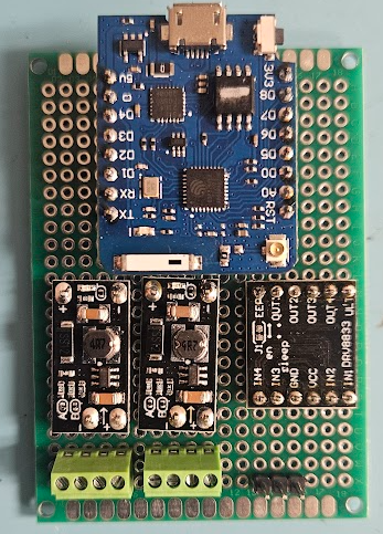
At the top is the ESP8266 board. In the middle are two boost regulator boards (more on that in a minute), a cheap motor driver board that will actually be used to drive the warning light, with room to drive a motor in the future. Along the bottom are connections for the battery, external power switch, sense switch for the punger and the light and finally, the header for servo to trip the sear.
With the power supply boards, I got a little too clever for my own good. They were spec’d out when I was contemplating 3.7V batteries. I don’t recall why I landed on 3.7 to start with, but I did. These boards take a 3.7V input and boost it to 5, 8, 9 or 12 volts, configurable by removing the jumpers A or B or both.
Somewhere in there, I decided to order 7.4V batteries instead of 3.7V. Luckily, I decided to test the voltages before firing up the board because running with 7.4V batteries, the he lowest available voltage is about 8 volts. I have 3.7V batteries enroute.
In other hardware news, I acquired a rather nice carbide metal cutoff saw. This thing makes amazing essentially mirror smooth cuts!


This 2×4 14ga tubing was cut in 10-15 seconds and looks like this!
This will definitely up the fabrication game.