A select few interested members of the shooting public saw the gadget yesterday. Reception was generally positive and a couple of suggestions will make it into future versions.
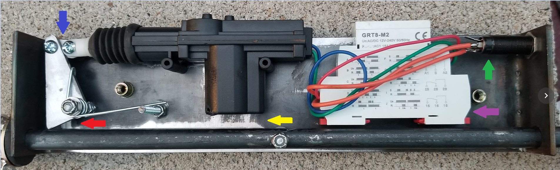
I was already going to remake this one to solve a couple of serious issues before it gets used in a real match in a couple of days, most importantly getting the pull rod away from the lock motor. I spent a good chunk of my Sunday doing just that. Behold the improved whickerbill:
Starting from the yellow arrow at the bottom center, there is now gobs of space between the pull rod and the lock motor. Incidentally, the case of the lock motor was actually breached by all the activations in show and tell yesterday. No internal damage was done. I will seal up that hole to keep dust and particularly shop metal shavings out of the very magnetic motor.
Proceeding clockwise, the red arrow points to the new longer but simpler sear. Rearranging things has let me avoid the relief cut that was in the back of the previous sear. The arrow more directly points to what is probably not an issue, but this is a more intense angle. I think I didn’t account for exactly how far I moved the rod when I moved the sear pivot. The sear pivot could really be moved another 1/4″ closer to the rod. It still works perfectly, but this is an area to keep an eye on and I will correct this in the next version.
Continuing clockwise, the blue arrow points to the new articulated link between the sear and the lock motor. I envisioned this in the original design, but just by dumb luck, the previous layout let me skip this link. The new layout requires it, plus it removes some binding strain from this point. This particular link was hand made, but there are some commercial options that I could leverage to save the time and effort of fabricating my own.
Next Vanna is pointing with the green arrow at the input jack, a heavy duty 1/4″ jack intended for speakers. This is not an actual Switchcraft Z15J (those things are rated for 15A!) but I do not expect my little motors and relays to tax it. The purpose, of course, is to make deployment easier. To that end, I also have some 50 foot speaker cables with 1/4″ plugs on either end.
Finally, the purple arrow is pointing to the timer relay. It was kinda halfass bolted down in a weird way on the rush-to-show previous box, but with the pull rod scooted over, there is room to more properly mount it using 3M VHB tape, which means I hope I don’t need to remove it anytime soon.
All this movement still fits nicely inside my 2×4 rectangular tubing, which I derusted with a Scotchbrite belt on the 2×72 grinder, but failed to take a picture of. Soon.
Speaking of fitting in the tubing, I used a seamstress measuring tape to measure the as-built length of the old chassis, from the top edge of one end, across the bottom to the top edge of the other end. Since this chassis is 5/8″ too long, I subtracted 5/8″ from this measurement and cut my new chassis to 14-7/8″ long with the newly secured Vevor shear.
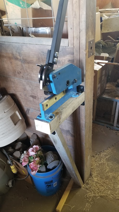
This shear is not even the biggest one they make and it is still kind of a monster. It chewed up my workbench top when I used it to trim a 3″x1/8″ flat by securing it in my bench vise. My first task this morning was to find this thing a place where it could live without destroying everything around it in use. I will one day figure out where in the workshop I can put it, but for now, it is mounted to a beam in the barn!
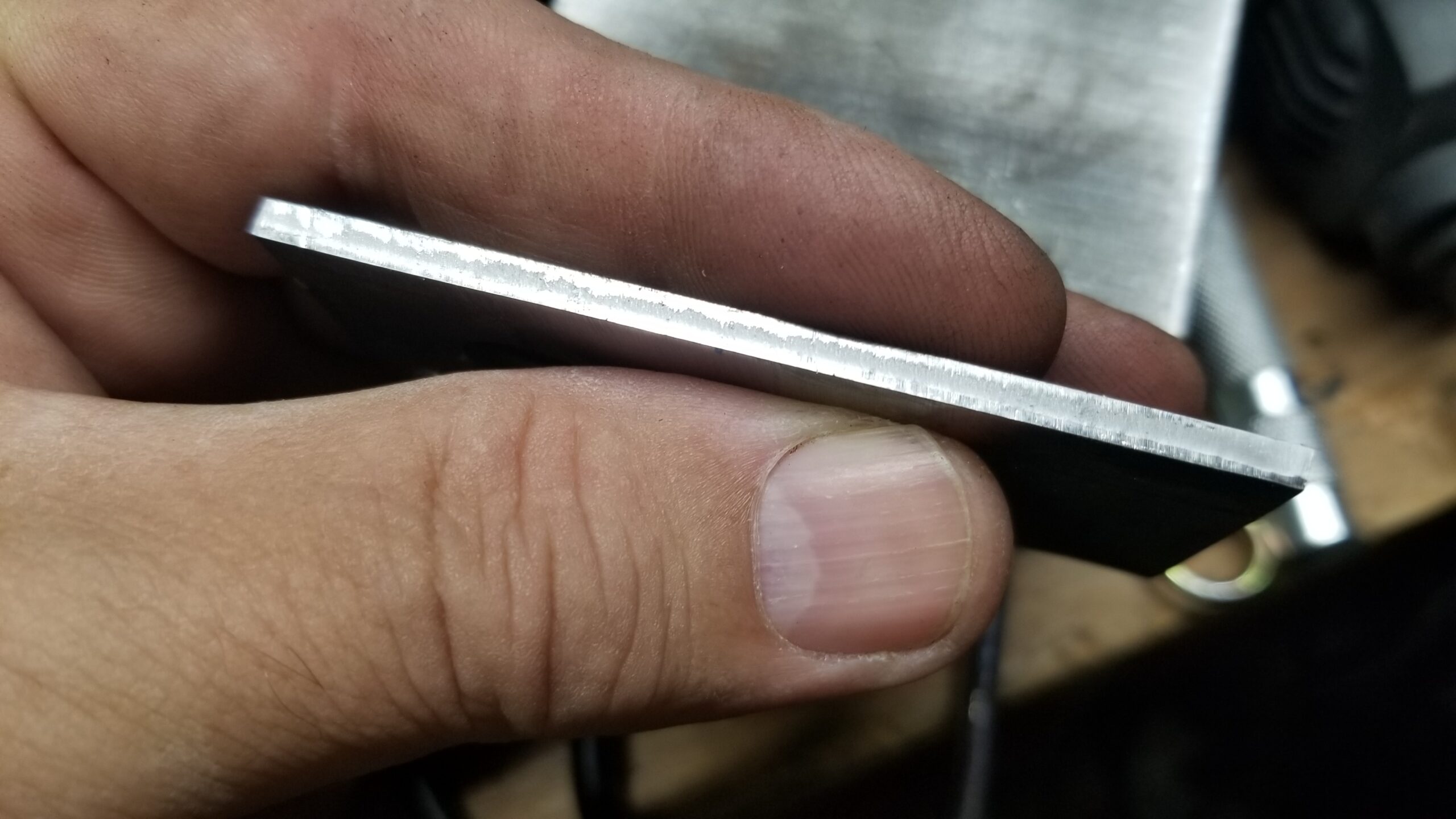
It does an outstanding job on this 1/8″ steel material, though I find that I do need to haul down on the handle with both arms for the longer cuts. That is more testament to one titanium shoulder and one iffy shoulder than anything about the shear itself. However, the shear does produce an excellent edge finish:
Thinner material or shorter cuts are just about trivial. The new sear was made in four cuts with the shear and minimal grinding.
Anyway, once I had the chassis blank cut to length, I measured the inside height of the ends of the old unit, marked that distance from teh ends on the new chassic and drilled holes to assist with bending. I fired up the acetylene torch, heated the drilled area and bent the ends. Everything went quite well.
I guess I didn’t account for the stretch on the outside of the bend when I measured and substracted 5/8″ to shorten the chassis. The new chassis ended up 12-1/2″ long, only 1/8″ shorter than the old one. I was aiming for exactly 12″ long.
The math kinda works. 1/8″ thick material in a 90 degree bend would intuitively stretch out 1/4″. I have two bends and my actual chassis is two times 1/4″ too long. I should have subtracted 5/8″ for the basic length to shorten and another 1/2″ since I was going to add two bends, so my flat blank should have been 14-3/8″ long to be 12″ finished length. We will see if that works out on the next one.
After discussing various match needs and ideas ideas and looking at some powered devices as they were deployed at the IDPA World Championship, it occured to me that it might be handy to make a device to reside downrange to activate movers electrically. The more I thought about it, the simpler the device became. Then, it got a little more complexity added back as I will need to protect people from themselves. 🙂
Conceptually, this device needs only the mechanics to yank on a cord or cable to activate a device and since it is downrange, it doesn’t have to pull 50-100 feet of steel cable, so it doesn’t actually need to be super strong. Electrically, it needs to trip the puller rod and not damage itself.
I gathered quite a few more parts than I probably needed, including a trip down a dark alley of cheap timers that I probably should have stayed out of. I drew up some rough plans a couple of different times to at least get a picture in my mind of what it should look like then in one quick evening of building, I threw together 90% of it.
Of course, being a prototype, there are some issues, all of which will be address by fine-tuning dimensions. For example, I cut the base plate presuming I would have 2 inch bends on each end to fit inside the planned 2×4 rectangular tubing I plan to use as a slide-in case. I remembered in time that the inside dimensions of that tubing will be less than 2 inches, so I shortened the bends to account for that. I did not remember to shorten the whole base plate accordingly, so now I will need a slightly longer piece of tubing for this particular unit. I had planned on just having the supplier cut me a bunch of 12″ lengths of tubing. Well, I am still doing that, just I’ll need to arrange a longer one for this one prototype, if I arrange any case for it at all.
There is room to move the pull rod farther from the unlock motor, especially since a spring will be pulling a bolt past this plastic part over and over and a collision seems bound to happen. Also, while it’s not a serious issue, the pull rod holes are not the same size. I used a step drill and drilled one step too far on the hole at the back. Maybe that is accidentally why is works really smoothly…
I am pretty happy with the sear design. Like everything, I hope to refine the dimensions and location to simplify construction. Originally, it had a nice, easy to grind, square corner. Unfortunately, to ensure that it clears the clevis on the lock motor, I had to cut some relief out of it, which means more time. There is room to move the motor more to the right, which will help that, but then the pivoting corner will no longer be square. One way or another, it will work out.
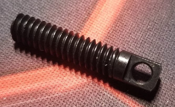
The pull rod has a simple notch filed into it. To arm, the rod must be in the correct orientation, which is marked on end of the rod. As a side effect, the pull rod can be disarmed without power by pulling and turning it slightly to disengage from the sear. A future design may have this notch replaced by a groove around the entire diameter of the rod. I will address this manual disarm feature in some other way, but the trade off will be worth it.
I have been gathering pieces and parts from all over, but a lot of it came from Amazon. Amazon is not typically the best price, but for prototyping purposes, it is very nice to click a few times and have it at your door the next day. I got stuff to do!
It doesn’t always work out, though. The heart of this mechanism is a car door lock motor. I chose that because it is fairly cheap, pretty strong pulling with about 5 pounds, and it does so without pulling gobs of power like a solenoid would. Since it is basically a brushed DC motor with some modest gearing, I can throw power to it to pull it in, then use a spring to pull it back out to the rest/locked position. However, many (or maybe most) of the ways to trigger a device for stage shooting purposes would result in power being applied to this fairly delicate motor continuously pretty much from the start of one shooter until make ready for the next. Few motors, but especially not cheap motors, survive that kind of abuse, so I knew I needed to apply power for only long enough to trip the activator then remove power until the next activation. This will also conserve battery power. In my day job, I have used timer relays for similar tasks, so that seemed the way to go. The timer relay I am using is a nice industrial lego part. This particular device has several modes, but I am using the “one shot” mode, which times out once for each application of power. I have it set for about a half second, maybe a little longer. So every time power is applied to the device, it will power the door unlock motor for about half a second, long enough to disengage the sear, then power it off until it is reset by dropping and reapplying power again. Simple and elegant.
This timer relay is the single most expensive part of this whole machine. Without it, the lock motor will fry. This relay is $36 via Amazon and typically more from Mouser or DigiKey or any of a handful of automation suppliers that I shopped. I did find the timer relays for as low as about $11-15 via AliExpress, which is significantly better, assuming everything one must assume about sellers on Alibaba.
I got very happy when I found some 555 based timer boards on Amazon for something like $1.35 each in lots of 20. I considered it worth trying and ordered one lot of 20. The boards came in and I found that they were easy to configure like I needed, apply power, disconnect after about 1/2 second, reset after dropping power. The first time I actually connected the lock motor to one of them, it immediately just started pulsing on and off every half second, even after I disconnected the motor.
Some electronics can be sensitive to inductive flyback. When a coil, which is basically what a motor is, has power disconnected from it, the collapsing magnetic field in the coil will induce a voltage of the opposite polarity in the connected wiring, often a destructively high voltage. This is great for the spark plugs in your car, but less so for $1.35 timer boards made in China. You can generally protect devices from this voltage spike with the application of a diode in the proper orientation, so I set up the second timer board with a protective diode in place. Never mind that there is obviously such a protective diode in place ON the timer board. Anyway, once the motor was connected, that timer worked about three times, then locked into a mode where it just turned on when power was applied, like all that circuitry did nothing at all. It became a complicated power indicator light. Maybe my 400V diode wasn’t big enough, but I have hundreds of them bought for the purpose and they have worked elsewhere.
Two out of two timer boards, toasted. I guess you get whatcha pay for. So, it doesn’t look like I am going to be able to use $1.35 boards to replace the $36 relay. Best I can hope for is that the $15 AliExpress relays due to arrive at the end of November are the same as the ones I have. Maybe I can find something to do with the other cheap timers, something that doesn’t produce an electric spike.
Hmmmm While editing this, it occurs to me that I have all the test equipment I need to see if this is actually the issue. I may tackle that because these little boards represent a lot of material cost savings.
Speaking of the timer and its effect on power…. I tested the timer relay, lock motor and rechargeable battery for endurance by running a simple test overnight. The battery I have used for all my development is a nice portable 12V 6000mAH lithium battery pack with a coaxial power outlet and a switch. As an aside, I have recharged this battery pack maybe 3 times between March and November and never because it was dead.
Anyway, I had the lock motor, timer relay and battery connected. I used a second timer relay configured in pulse generator mode, set to trip once every 30 seconds and wired to trip the other relay and the lock motor. Once I had that running, I left it on the workbench overnight. The next morning, about 6 hours later, it was still running. In 6 hours, the relay (both relays, technically) and lock motor had cycled about 720 times. The battery was between 40% and 60% charged. That day was one of the times I charged it back up.
Before I settled on a 30 second interval, I had it triggering much much more rapidly, but I found that both the lock motor and the relay were getting warm to the touch and the lock motor uncomfortably so. Running it so rapidly mean that it spent more effective time at stall, especially as in that testing scenario, there was no return spring on the lock motor plunger, so it would have spend more time in the fully retracted stalled position. Slowing the test to 30 seconds was a little more realistic, giving the motor rest time between shooters, but still let me run many hundreds of tests.
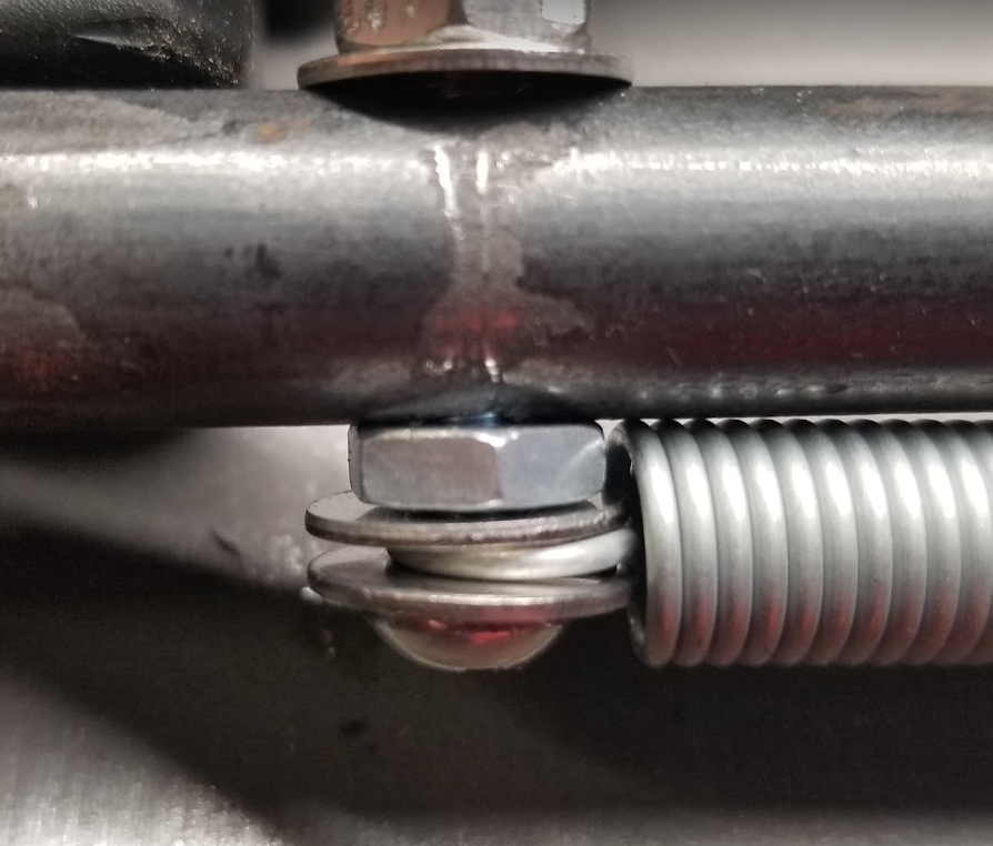
I happened to source some springs from Grainger, including some 6 inch main springs. I am attaching the spring to the pull rod with generic 10-32 hardware. There is a nylon lock nut up top only partly visible in this shot.
The other end is currently connected with the homebrew version of a spring anchor, which I didn’t realize was a big enough thing to have it’s own specialized distribution industry.
Mine was made by grinding flats on either side of a #10×32 screw then drilling a suitable hole in it. Note that my drilled hole not well centered, so the 1/4×20 factory made screw anchors I just picked up today will probably work out better or at least last longer. They were surprisingly expensive at $5.70 each, but then: Grainger.
Not much cheaper anywhere else, but I can at least find them smaller than 1/4×20. On the other hand, short 1/4×20 machine screws are really cheap and would arguably be easier to make into homebrew spring anchors 🙂
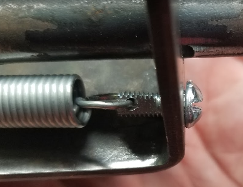
The locations where my lock motor and sear ended up limit the available space to use an extension spring for the sear return. I found this torsion spring at a local hardware store. I was able to modify one leg to keep it from slipping off the sear and I added a screw to use as an anchor for the other end. I also had to change out the sear pivot as I had trimmed the original to length.
It works perfectly! I may seek out this spring for the permanent design.
This image also really shows how close the pull bar and the lock motor are and if you look in the shadows on the left side of the lock motor, you can just see where the pull bar spring anchor has gouged on the plastic case.
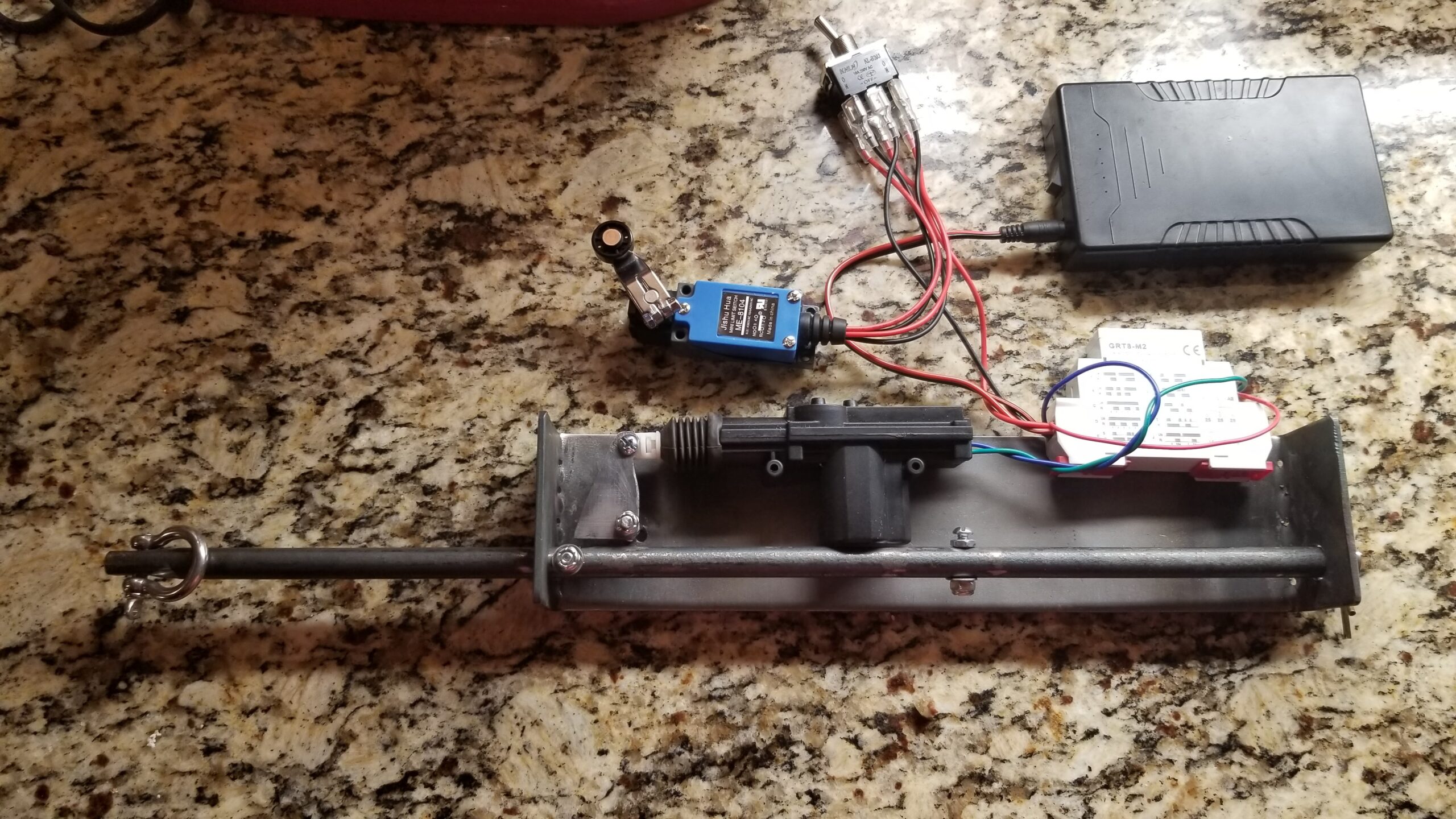
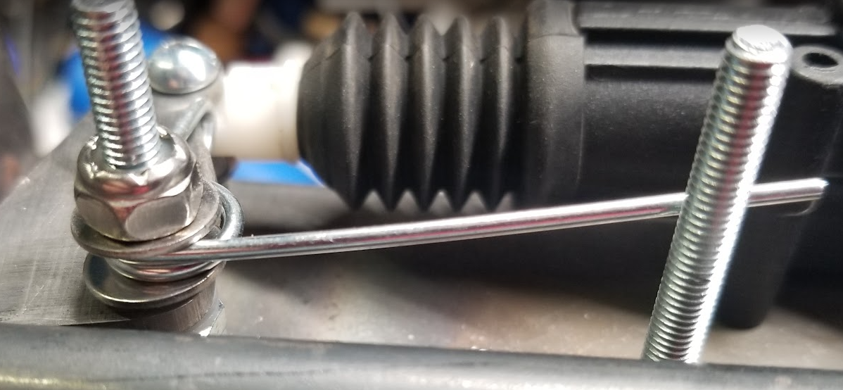
In a little wider view, here is the meat of the mechanism. At this point, I still have the step plate switch wired up, but that is just because it was easy to leave it in place while working on the electromechanical bits.
It is unclear how helpful the shock absorber really is, but it consists of a thick rubber washer backed up with a grade 8 steel washer. The grade 8 washer might be overkill, but that’s my favorite kind of kill.
At the point where the sear latches, the rod and spring is pulling just over 12 pounds, which should be enough to activate any mover I have personally ever come across. I have my force gauge in my gear bag so that I can measure the required pull of any movers I find in the field. I also have a (very) small army of field operatives making similar measurements.
Before this particular unit gets exposed to the public in hopefully less than a week, it will undergo three fairly major changes.
First, I need to move the lock motor away from the pull rod. As predicted, the motor gets hit every time by the screw attaching the spring to the pull rod. It only needs to move a small distance, though I need to keep the full width of the chassis under 3.75 inches to fit inside the 2×4 rectangular tubing case.
Since I brought it up, next is the case. It might be important to point out that the unit as pictured here will be mounted upsidedown in the case so that mounting bolts will be on top of the case instead of on the bottom. This will be better for indoor use on concrete floors. I have ordered some steel, including 2″x4″x11ga retangular tubing, 3″x1/8″ flat bar and 1/2″ round bar to have plenty of components to make more units. I have ordered them precut as needed, so that should help cut down on time and effort. As I write this, my steel order might be ready today, but probably not until tomorrow. There is, however, every chance that this specific unit may not end up in a case
Finally, I have a little rewiring to do on this unit. The beartrap details are not needed for it, but I would like to add a terminal strip and a protective bridge rectifier to keep a future yahoo from connecting the wiring backwards. I think the timer relay may be build smart enough to tolerate that, but why risk it?
I would also like to build an accessory box to make it easier to connect a variety of triggering minutia to the system. Basically, a box containing the battery and a couple of switches. It could easily fit into an ammo can. First a switch to enable/disable the downrange device so that no matter what someone does with a triggering device, it will not trip the activator. It would be nice if this had a bright flashing red light near the start position of the stage to warn that the activator is not enabled. It will also have an input “polarity” switch for choosing whether the activator responds to closing a contact or opening a contact. A dead man switch or step off plate would require a closed contact that opens to trip downrange. A step on plate or a photo electric bean would require an open contact that closes to trip downrange. This function simply requires the relay to translate invert the normally closed contact operation. Another timer relay might be deployed to ensure that devices with really short closures would still reliably activate the yanker. An adustable delay could be added so that activation does not occur immediately when the trigger even happens. Finally, this box could even provide an easy source of 12V power for devices that might require power such as photoelectric detectors.