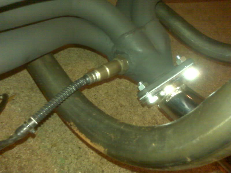
I got the chrome stinger and baffle on the way home from work. It seems almost silly to pay $40 for what is essentially a slightly flared pipe with a flange, but I couldn’t make one anywhere as quickly as I picked one up. It is the swivel type and bolted on nicely, though I didn’t cinch it down permanently. I will need to remove it to drill the stinger and baffle for a retaining bolt. Sadly, this counts as the best picture I took of it. I will take a better one in the daylight and replace it.
I carefully but temporarily placed the bumper to test the clearance with the new O2 sensor bung. It clears nicely!
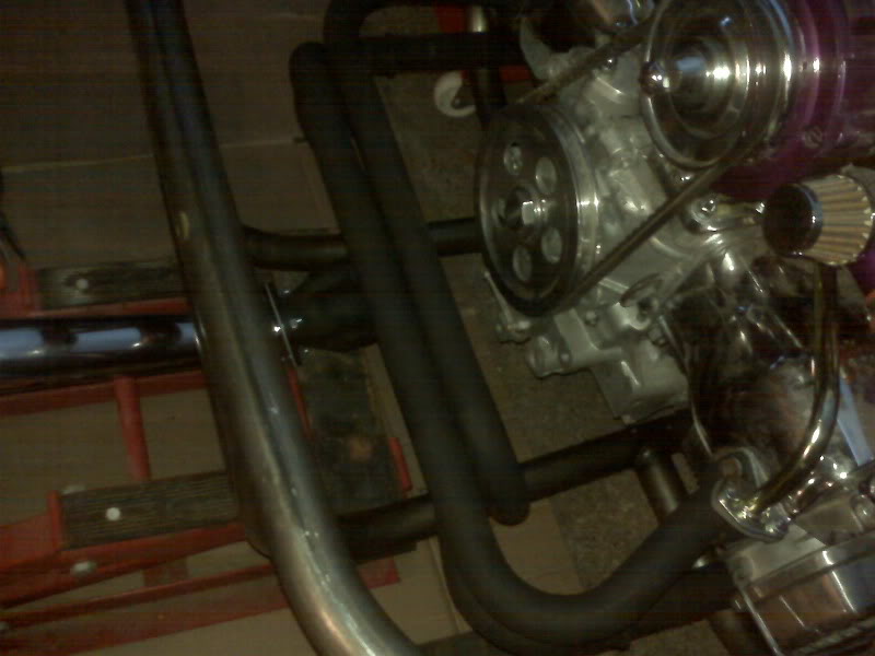
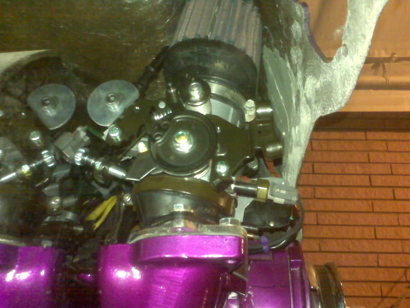
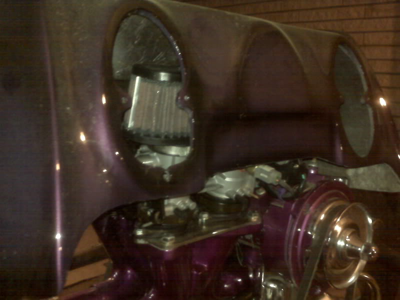
I dropped the body on to the frame to make sure that it clears the bumper. While it was there, I checked clearance at several other key points, such as the throttle body and air filters, the body mount under the driver seat (which will need about 1/2″ of shimming and the nose. I also looked around for open space for mounting the EFI controller. The jury is still out.
With the fit verified, it was time to make the permanent fitting for the bumper. The first step was to bend the upper mounts to coincide with the angle on the shock towers. With my anvil back in place, that was nearly trivial. I would rather have bent them hot, but I was pretty sure my torch is not big enough to heat as large an area as needed.
Of course, one shock bolt was in “backwards”, at least for my preferred mounting orientation, but it was easy enough to flip. When the bumper comes back from powder coating and is permanently installed, I will need to switch the bolts out for some that are slightly longer to account for the bumper and the washers it needs to be mounted with. I may even set it up such that loosening the bumper nuts won’t affect the shocks. Anyway, I snugged them down tight enough to stay, but loose enough to adjust if needed. I squared and leveled the bumper and made a few measurements to be sure it was as well centered as I could get it and tack welded the bumper to the upper mounts.
The lower mounts will secured with pins so that the bumper can be removed without dropping the transaxle and engine, which I nearly did accidentally with the yellow trike!
I lugged the bumper back to the bench and welded all around the top mounts and dressed the welds in preparation for powder coating. I rounded the corners of the bottom mounts, especially the ends of the tabs that go under the big bolts. I also welded on a license plate mount.
One thing I neglected was to drill a couple of holes in the top tube of the bumper for wiring. They can be drilled after powder coating, but it would probably be a neater job to drill them first.
My plan is to have a 2″ receiver hitch on the bumper. The way the stinger fits, it will be nearly impossible to use right away, but I think I will go ahead and put it in anyway, the long term plan being to have a custom exhaust that will clear the hitch. The biggest trailer it should ever be pulling is a small motorcycle cargo trailer, so it doesn’t need to be rated for 5000 lbs, but I like the flexibility of the 2″ receiver. Besides a tow bar, I can put a cargo tray or a bike rack or even a grill.