I haven’t been excited about a hardware project in a while, mostly because I haven’t really had a practical application that needed doing.
We have a 400-something foot deep well that produces really nice water. It does have a bit of sand that we need to filter out and all that is pretty well addressed by now. According to metainfo on the pictures I took, I installed a water meter in our water system in May of 2012. I chose a unit that included a pulse output so that I could connect it to something to electronically track our water usage. The pulse output is really just a magnetic reed switch operated by a tiny magnet on the 0.1 gallon dial. It closes the reed switch once per revolution, thus ten closures per gallon. The pulse unit is removable and not pictured here, though you can see the magnet on the x0.1 dial.
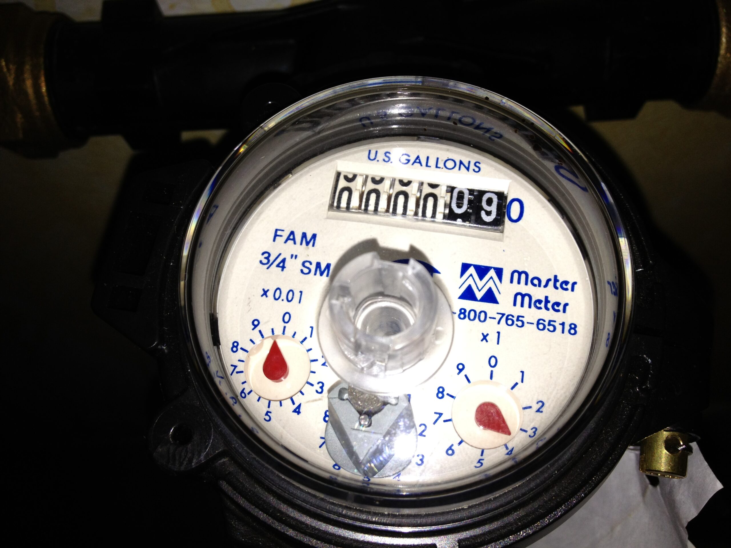
Incidentally, between May 2012 and the time I am writing this, we have used almost 247,000 gallons of filtered water.
Unfortunately, nothing available to me did a good job at counting and accumulating those pulses, not anything I could buy for a decent price. I had an electronic counter connected to it for a while; it was just an accumulator with no connectivity to anything. It’s battery has LONG since died, but I disconnected it to connect the board described below. I need to put a new battery in it and see how far it got. 🙂 There are professional data acquisition modules that do the task, but not for a price I was willing to pay. When I was shopping for stuff at CloudFree and saw these little ESP8266 boards, especially for $3.50 each, I looked into them. Wow.
The ESPHome project is an entire ecosystem built around a family of boards using the Espressif family of microcontrollers, ready to deploy in Home Assistant. In short, people way more brilliant than I am have done all the hard work and have modularized home automation functions so that with a few lines of configuration, one can set up these boards to do a wide variety of complex functions, interfacing with hundreds of off the shelf input and output devices. You can combine whatever you need in essentially limitless ways.
What mattered to me immediately was the Pulse Meter Sensor. It was original intended to attach to electric meters which provide a pulsing indicator for consumption, but by tweaking that default configuration just a little, it tailors it nicely for water.
After a bit of experimentation, the configuration to read my meter is as follows:
sensor:
- platform: pulse_meter
pin: 13
unit_of_measurement: 'gal/min'
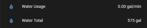
name: 'Water Usage'
internal_filter: 100ms
accuracy_decimals: 2
filters:
- multiply: 1
total:
name: "Water Total"
unit_of_measurement: "gal"
accuracy_decimals: 0
filters:
- multiply: 1
The decoder ring: Pin 13 is descibed in better detail below.
The ‘unit_of_measurement’ is just the text describing the units reported. It doesn’t actually change what the units are. You could call it ‘cubits of sanskrit’ and it would still give you the same numbers you configure it to deliver.
“internal_filter” is essentially a debounce timer in this application. It tells the counter to ignore any pulse shorter than 100ms.
The accuracy_decimals directive is the number is digits right of the decimal to deliver. The meter rate is calculated as a rate per minute, so it basically measures the time between pulses and calculates the rate based on that. So long as water is flowing, it’s reasonably accurate. Kinda weird that once you turn the water off and its not getting any more pulses, it still reports the same flow rate because it’s not changing. There may be a setting to address that. If you wait long enough, the rate drops to 0, so there probably is a timeout value.
Since my meter outputs one pulse per gallon, the ‘multiply: 1’ lines are redundant, but I left them in from earlier failed experiments and for clarity.
For ‘total:’ this is a running total of gallons consumed. Since it is always in whole gallons, there is no need for accuracy_decimals and again, muliply by 1 is just there for clarity.
My board looks almost exactly like this one:
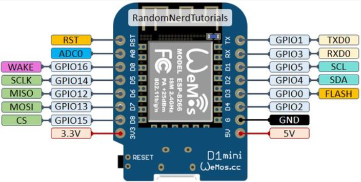
There is a little confusion (for me, anyway) as to what one should call the various pins and which ones are ok to use under what conditions. Some of these pins are asserted internally at boot time; some will cause boot to fail if they are asserted externally. Some are used when communicating with the chip. Long story short, the four pins highlighted in green are generally safe to use under all conditions. I am not sure why I chose 13 instead of 15. Shrug. I am equally unsure why the board designers put D0,D5,D6,D7 & D8 for GPIO 16, 14,12,13 & 15. I’m sure there is an engineering reason. Whatevs.
I put a 10k ohm resistor between D7 and 3V3 to pull the GPIO13 pin up, then connected the pulse output between D7 and GND. It works perfectly.
Flushed with this initial success, I decided to add a second pulse meter sensor to this same card. The water meter above is after all the water filtering, right before the treated water goes into the house. I have also tapped off before the filtering to feed water hoses outside with significantly higher pressure and flow. This water is, of course, not metered. I have another meter very similar to the one feeding the house, but this is not such a critical feature and I don’t really need the ‘odometer plus pulse’ meter. I can really get buy with just the pulse counting. Besides, that other meter was really intended to be a spare for the ‘main’ meter.
I found a cheap water flow sensor on Amazon and as I write this, it (two of them, actually) are due to arrive tomorrow. Plumbing it in should be pretty simple. The ESP8266 board has 5V available to power the flow sensor. Wiring the input will be a little more complex as the flow sensor is a Hall effect device with a 5V output and the ESP8266 board has a 3.3V input. They are reputed to be fairly 5V tolerant, but even a $3.50 board doesn’t deserve to be smoked just because it’s cheap. The easiest way to accomplish this level shifting, especially with the fairly low bandwidth needed for these frequencies, is a simple resistive voltage divider network.
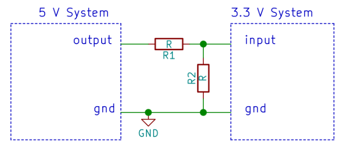
Whatever value chosen, R2 will be (so close as it doesn’t count to) twice the value of R1. I will probably start with the venerable 10K for R1 and likely two 10K in series for R2, because I have a cubic buttload of 10K resistors laying around. If the output of the 5V system is indeed 5V, then the junction between R1 and R2 will be 3.3V. The only factor that might affect that is if the 5V output can’t provide enough current or if the input for some reason sinks a lot more current than anticipated. In all, it’s expected to be fine.
If I understand the specs correctly, this flow meter gives a frequency output of 5.5 x the flow rate in liters per minute. Those multiply lines in the sensor config will mean something now. I have done some scratchpad math and arrived at the following pulse meter configuration:
  - platform: pulse_meter
    pin: 12
    unit_of_measurement: 'gal/min'
    name: 'Unfiltered Water Usage'
    internal_filter: 100ms
    accuracy_decimals: 2
    filters:
      - multiply: .048
    total:
      name: "Unfiltered Water Total"
      unit_of_measurement: "gal"
      accuracy_decimals: 0
      filters:
        - multiply: 20.82
As I write this, I cannot recall exactly how I came to these two multipliers, but I know that 3.78 liters per gallon and 5.5 x the flow rate were both involved. I strongly suspect that some empirical testing will be in order as well.
Also, a chart I saw indicated that at some higher flow rates, the output can be 60Hz or so. This will be getting pretty close to the 100ms internal filter pulse width. On the other hand, hopefully the Hall effect output is already debounced, so that filter may be redundant. We will see.
Furthermore, I will also be adding a flow sensor to the inlet of the water heater to monitor hot water usage, with it’s own board. Perhaps I can be clever enough to subtract that amount from the total usage somewhere.
The time has come for my confession.
I have described the ESPHome experience as it should have been, almost plug and play. It did not go that way and it was NOT because of ESPHome.
I was very excited to get that first board plugged in and make it go. The process sounded very straight forward.
Install the ESPHome Dashboard on Home Assistant. Trivial, done.
Open the ESPHome Web UI, click on Add Device…
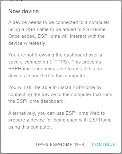
Ooops. Well, no BIG deal. Adding an SSL certificate is something I need to do someday, but I can just do this from the PC I’m using instead, so I click on the ESPHOME WEB link.
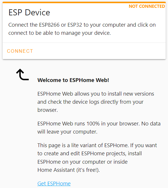
I get this page, I plug in my cable with the board, click on the CONNECT link and this is the last time anything good happens for a looong time.
It pops up a dialog wanting to choose a device to connect to, but none of them look like anything new or appropriate. I open Control Panel and nothing in Device Manager looks like a new thing, except for that one thing that says it’s not functioning because Windows can’t find a driver for it. I unplug the board, it goes away; plug it in, it comes back. Sigh.
I Google, find the [hardly sketchy looking at all Chinese] driver download page, run the self-installing driver, hoping that all my anti-virus software is up to date. It appears to install.
No change.
I try it on what eventually turns out to be three other computers. Nothing different. And apparently no viruses. Win?
Finally, something I *swear* I saw somewhere suggested plugging it into the Home Assistant hardware to try it from there. Maybe I dreamt that. I had more ports in the USB hub, so I plug it in. I consult the VM to see if it is there and ready to be allowed over. No, just the Zigbee and the Z-Wave.
I wonder if somehow I am limited to two devices by the virtual machine manager, so I unplug the Z-Wave dongle and plug the ESP8266 back in. It still doesn’t show up anywhere.
To be completely honest, the ESP8266 and the Z-Wave dongle were alternatively plugged in and unplugged multiple times during this process, sometimes both plugged in, sometimes to the hub, sometimes to the front panel USB. I probably put one of them in my ear and the other in my anus at some point, just to see if that would help.
By this time, I have spent a few minutes here and there during three hours of the workday and four solid hours that evening trying to get this awesome little board talking and I’ve reached a point where I am both too tired and too frustrated to go on, so I put it away and do something else for a while, probably involving alcohol.
The next evening, I start in on it again, but my fresher eyes realize that I did all this testing with the same presumed good USB cable. Afterall, it definitely shows up when plugged in and goes away when unplugged, it just couldn’t find the driver for the device. So, I walk 8 feet across the room, grab a different USB cable and plug it in.
Comes right up, CH340C on COM3. ESPHome sees it, connects, uploads adoption code. Everything I do with it from this point forward works like it’s supposed to. I try the ESP32 board, works perfectly, but it’s drivers (CP210X, like the dongles, ironically) are already installed in Windows.
All because the F&*%ING USB cable was not 100% bad.
[insert all the ESP8266 success story related above here > ]
NOOOOOOWWWWW…….
A couple days go by and I notice that the driveway light switch, the lone working Z-Wave device currently on Home Assistant, is not working. I have a Zooz multirelay configured, though not deployed, but it is also not working. When I dig deeper, I find that the controller is down. As I’m sure you can predict now, I spend several days trying various things to get the stupid dongle to come back up. I even reach a point where I am contemplating abandoning all Z-Wave and going all WiFi and Zigbee. It’s not a trivial decision; I have a box full of unopened Z-Wave stuff, including a spiffy new scene controller I have just purchased that I have specific plans for.
I was able to verify that the dongle itself was working. The Silicon Labs tools included some network stat tools where you could view a count of packets send and received. I had it installed in my laptop, took a snapshot, waited, took another, waited, etc, just to verify there was no regular traffic. Then I plugged in a multirelay device and there was a burst of traffic between it and the dongle. Reasonable expectation of functionality.
Among the things I tried was viewing lsusb and dmesg from the terminal of the VM. Trouble is, because this is Alpine Linux, this isn’t really lsusb and dmesg binaries but their lobotomized BusyBox equivalents, so most of the usual switches that could add more details to help figure stuff are not really there. Not that I am any kind of ace at troubleshooting Linux issues anyway. I have had the perhaps unenviable position of being more of a Linux power user rather than a sysadmin. My (mostly Fedora) systems have for the most part always just worked and I have rarely had to fix anything on them, so I don’t have just tons of breakfix experience with it. If it doesn’t break, you never need to fix it.
In any case, it turns out that the “solution” appears to have been to let something time out. The last thing I did was a reboot of the VM with the dongle removed. I added the dongle to the USB hub, but for whatever reason, I didn’t immediately allow it through to the VM. Some undetermined time later, a day or so, I sat down to prove that I am indeed insane only to discover that it needed to be allowed through to the VM. I did it and suddenly, lsusb listed another CP210 device and dmesg showed a new USB device found and Z-Wave JS UI showed /dev/ttyUSB1 available.
Now it works again.