What I am making is not particularly innovative, but I am combining elements I have seen only in separate devices. I’ll be less opaque:
In various competitive shooting sports, there are ways to activate a moving target or other device downrange at some point in the course of fire. Sometimes the competitor just pulls a cord, but there are several devices available from different suppliers to accomplish this automatically, usually by strictly mechanical means. One common example is the Pressure Plate Target Activator from MGM Targets. Operation is simple and reliable; pull the rod out and rotate the trigger flag to the set position and gently close the cover over the flag. When the competitor steps on the plate, it trips the trigger and one or more springs yanks one or more rods. The rods are typically connected to cords/cables/strings that actually activate the moving target downrange.
I personally have only seen devices that trip when they are stepped ON but I have heard of units of a similar but obviously different design which trip when the competitor steps OFF of the plate. I think it would take a significantly more complex design for one device to do both.
I have also seen devices where the cord yanking is triggered remotely by an electrical solenoid. Such devices are frequently activated by something other than stepping on or off a plate, such as requiring the r a competitor to press and hold a switch. When they move and thus release the switch, it triggers the cord yanking device wherever it is. A great example was at the 2022 IDPA National Championship match. In this video, the competitor’s hand is holding down a switch. When the timer beeps and they release the switch, a timer relay somewhere would delay a couple of seconds then fire a solenoid to release a disappearing target.
Sadly, the moving cardboard target against the sandy soil is almost invisible to the camera. This video shows the target somewhat better.
The downrange activator works like this. This was the actual spare unit for the stage shown in the videos above.
Once activation is electric rather than purely mechanical, now it’s just a matter of wiring and switches to change between step on or step off, tripping a local or remote activator, triggering it by some other device or any combination of these. This is my contribution to the art.
I acquired two devices to test the activation, an open frame solenoid rated at 25 Newtons. That translates to about 5.6 pounds of pull, but solenoids are somewhat tweaky about exactly where in the travel of the plunger you can expect full pulling power. The specific units I got are no longer in stock, but this similar unit would probably be more suitable anyway.
Car door lock actuators seem like a great match. They are actually geared motors pulling or pushing with roughly the same force throughout their travel. I got a set of four for $18, vs the solenoids, which were $14 each. The lock actuator is slightly slower than the straight solenoid, but not enough to be significant.
There are two trigger switch options that seem largely interchangeable, depending on how one designs the step platform. One would be a momentary pushbutton switch. If mounted sensibly, it could be protected from rough treatment such as stomping the plate and they are available in a variety of forms and wiring options. However, before I thought about that, I found that I like the roller lever concept and I got 4 of them that are designed as limit sensing switches for industrial equipment. They are dust sealed and potentially water sealed, both of which could be important for a device that is sure to see service in the dirt and mud and rain at a match. Interestingly, this switch is not a double pole single throw switch, but rather it has separate normally open and normally closed contacts. This slightly clarifies the wiring by providing separate step-on and step-off contacts. If it were a typical DPST switch, however, it would not make any operational difference.
My design always included a timer relay to limit how long power is applied to the actuator. The electrical bits could be tripped by a simple switch closure, but most scenarios would leave the actuator powered for most of the entire time between competitors. Solenoids and motors get hot and fail under such conditions, plus you are wasting what is sure to be battery power. I got a multifunction relay, but the mode that works for this is called One Shot. Power is applied and the actuator immediately activates. After a programmable delay, less than a second typically, the output turns off and releases the actuator. It stays in this state until power is removed (by resetting the sensing switch) and it’s ready to fire again.
In this short video, I have wired it up for testing on the bench. The switch is configured for the step off mode:
Since this test, I have added a toggle switch to select step-on or step-off mode for testing and have listed the elements that I intend to include:
- Power Switch
- Two fuses
- Trigger Switch: Local or Remote
- Remote Trigger Contact or Voltage
- Remote Trigger Contact Polarity Switch: Normally Open or Normally Closed
- Activator Switch: Local or Remote
- Remote Activator Mode Switch: 12V or Dry Contacts
- Remote Trigger jack
- Remote Activator jack
I have a tentative diagram that was drawn before this list. It is missing a lot of details, but it has many of the components:
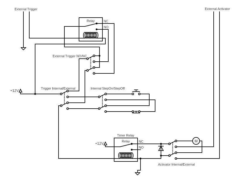
The free online CAD I used to whip this out wasn’t super flexible. For example, all the switches are oriented the same way and being able to flip it over could make big diffence in the layout. Similarly, although conceptually, the timer relay can be represented as a standard relay, especially in the mode I am using, other modes would require constant 12V supply connection. Lucky me! There are better circuit CAD applications, especially those provided by printed circuit board providers. More on that later.
The switches I have chosen for most of the switches are DPDT toggle switches that have a center off position which serves to disable the action it switches. These specific switches were chosen because they are physically large and presumed to be fairly resistant to abuse by the mostly general public who might be working with them.
The electric bit is all but completed in design, but a big part of this thing is the physical platform itself. Most of the existing designs are fabricated from various sizes of steel angle for two basically concentric frames and generally some kind of plate or expanded metal for the stepping surface. The top plate is generally on the larger frame and they are joined by hinges, sometimes commercial but usually also fabricated.
I have spent way too much for prototype materials, mostly because I could not find a decent opportunity to go to local a steel supplier and ordered material online. Steel plates are heavy and steel angle is supplied in lengths and is heavy, characteristics that substantially increase shipping costs. The steel was about $80, shipping about $50. A local supplier will be significantly less and there will be no shipping.
My plan is for the step plate to be 18 x 18 inches outside dimensions the bottom frame to be enough smaller to fit the step plate well. I am expecting it to be 17 to 17.5 inside dimensions.
I cut my 72 inches of 3/4″ x 3/4″ steel angle into 18 inch pieces with mitered corners. As 18 goes into 72 exactly 4 times (minus about 5/16″ total saw kerf), it’s just barely enough for the top, and in fact, the 18 x 18 tread plate is slightly larger than the frame pieces and will need to be trimmed to fit. Technically, it will be slightly rectangular rather than square, but only by about 1/8″.
Since the frame will need to be a little smaller anyway, the 72″ length of 2″ x 2″ steel angle will fit slightly better, though as these will be outside corners, I would need more than a foot more material to cut proper miters. This will not be a problem with the version 2 prototype or production, but for the prototype, I will need to make square cuts instead of miter cuts and probably will want to fill the outside corners.
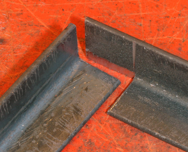
A coping joint could be easier than a miter. This image is of an inside corner, but illustrates cutting a cope in material to be joined.
Once the upper and lower frame agree on size, I will need to hinge them together appropriately
In the interior of the frame, I will need to supply various surfaces for mounting components. These substructures will also help reinforce the frame and keep it square.
Specifically, I need a place for the battery, a place to mount the trigger switch, the timer relay and the actuator assembly, including the rod and spring. Finally, I need a panel appropriate for all the configuration switches and the external connection jacks.
Once I have a working and tested prototype that I can take dimensions from, streamlining for production should be exciting. If there is ever a chance for these things to be profitable, it is going to have to cost less money and time to build each one. This is likely to be an iterative process, where doing one thing at less cost is likely to require a change in some other part of the design, which may itself affect cost again.
The most effective cost cutting method would be to buy my components in the most cost effective manner as possible. Note I did not say as cheaply as possible. My electrical components thus far have all been sourced from Amazon because it’s really easy to find stuff and I don’t have to go anywhere to get it. I will likely be able to weight the differences between cost and form factor and find entirely suitable components that cost less, especially in some quantity.
Similarly, once the frame size and components are determined, I may be able to design and order CNC plasma or laser cut parts. The cost savings for such parts will depend on dramatically decreasing the time required to assemble the frames. Using steel shop primatives like steel angle and rolled plate means lots of measuring and cutting of raw materials, preparing them for welding, welding them together, cleaning up the welds then finally applying a finish. With CNC cut parts, the pieces can fit together and require a handful of tack and stitch welds, taking far less time to complete. Laser cut parts will require minimal preparation, but plasma cut parts might be enough cheaper to offset that. With either, I can use a minimum amount of thinner material, converting less raw material into waste and eventually saving shipping costs.
So, I will probably do that.