Ok, *they* call it ESP-Now… or ESPNOW… or maybe it’s ESP-now…
Point is….
Espressif makes some chips now and then. Maybe a bunch of them. Chances are pretty good that if you have something in your house that does WiFi, especially if it is an IoT thing, it likely has an Espressif chip at the heart of it.
My gateway into ESP was the ESPHome platform in Home Assistant. I have a couple of ESP8266 based boards gathering and reporting information back to my Home Assistant. One is a pretty simple temperature sensor that reports the outside temperature, or at least the temperature *just* outside of the garage door. The other has two active inputs, a temperature sensor that tells the approximate ambient temperature around my water system, which consists of a a bunch of overcomplicated plumbing in my garage, and the water flow rate and total consumption for the house, based on what a flow sensor equipped water meter is willing to share. This unit also has two inputs that I have not yet connected that are detailed in the other blog post.
To the point, I am at least somewhat familiar with the ESP8266 based Wemos D1 Mini board. This is a 1 x 1.5 inch board with the surprisingly powerful ESP8266 microcontroller on board. ESPHome hides a lot of the ugly details from you, but the ESP8266 is a general purpose microcontroller with built in WiFi support and a handful of general purpose IO pins. It is essentially a single core version of the ESP32 with a little less I/O and a (only) 80MHz clock.
Remember ESP-NOW? This is a post about ESP-NOW….
ESP-NOW is, to paraphrase the documentation somewhat, a hijack of the typical WiFi TCP/IP stack. ESP-NOW uses the hardware of the MCU’s WiFi facilities, but at a not the whole stack. It lives and communicates at layer 2 of the OSI model. It is a peer to peer protocol, with no need of a WiFi router, DHCP or any of that sort of thing.
This protocol leverages the ‘action frames’ element of the 802.11 standard. This subprotocol is generic, but often networking gear of any given brand uses this protocol to communicate between themselves. For example, action frames are how access points in the same SSID pass your roaming device between different access points, with vendor specific data passed as action frames.
This protocol comes with some limitations, such as a limit of 250 bytes per packet. For most such purposes, 250 bytes is way more than needed most of the time. I need to pass only one or two bytes as my payload.
If you want to skip a bunch of background and exposition, you can scroll down to the big Espressif logo.
I was killing the usual time on YouTube when, based I’m certain on browsing habits that include ESP8266 stuff, they presented a couple of ESP-NOW basic configuration guides. My application has been begging for a wireless connectivity method and here it is, dropped in my lap and almost perfect for my needs.
Without getting too detailed, I am building a system which needs a controller that can see an initiating action and trigger the activation of some hardware. Specifically, I am a competitive pistol shooter. The main sport I am involved with includes scenarios wherein you may have to address targets that are moving or may have non-threat targets moving in front of them. Historically, these moving targets have been triggered by simple mechanical means, such as stepping on something that will trigger a spring loaded device to yank a cord/cable in order to activate the moving target. At this point, I have a working and reliable system that operates electrically. It has been used at several matches for a little over 300 activations, with no mechanical or electrical failures. So long as it is reset between stages, it just works.
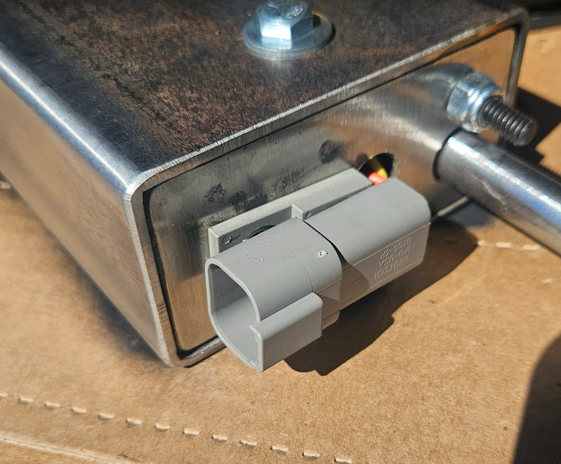
I have build a version 2.0 of the same device, with almost identical mechanics, but with a four conductor connectors and cabling for reasons detailed below.
This unit has only been to one match, but except for the occasional failure of the humans to reset it, it performed perfectly.
The issue is, of course, everyone wants just a little more out of it, including me. I mentioned “So long as it is reset between stages…” and that is a fairly common issue. Failure of stage equipment to activate results in a mandatory reshoot for that competitor, which costs everybody time.
For example, a given competitor decides to be the one who resets the device. When that competitor is coming up in the rotation, generally for at least two competitors before him, he is not actively resetting the stage. If nobody notices at first, the activator doesn’t get reset.
When the next competitor goes, whatever is supposed to trigger the activator doesn’t seem to do anything, so that competitor is commanded to stop and reload to make a new attempt. Once this kind of thing is happening, it tends to snowball into two or three competitors in a row having some kind of problem and the root cause is that people didn’t notice that the activator was not reset.
Another, though lesser, issue is when resetting the stage and someone *has* reset the activator, but someone accidentally walks through the triggering area and prematurely sets off the moving target.
Let’s list our grievances…
- Nobody notices that the activator has not been reset.
- It is clumsy or impossible to guard certain kinds of triggers from activating while the stage is being scored and reset.
- I haven’t mentioned yet that everyone wants this to be wireless, too
- Ultimately, it would be great if the activator could reset itself.
I added the extra wiring to the activator with the intent to have a switch inside the unit that is closed whenever the unit has been tripped and thus turn on a big red light at the controller whenever it needs to be reset. While I haven’t actually figured out the best switch arrangement yet, the idea is otherwise fairly trivial to accomplish.
Triggering the activator wirelessly is something I have experimented with. The best analog solution I found for that is a wireless system intended to operate a gate from a remote button. The receiver is relatively small and can be powered by 12V. The remote is a typical handheld door opener button, but would be pretty easy to modify to attach to the control box as it currently operates. The bad news is that this wireless set is about the same cost as my build cost for an entire system, essentially doubling what I would need to charge for it in a finished product.
However, and I’m sure the reader is tired of all this exposition by this point, I do have a solution.
For reliability reasons, I did not first pursue microcontroller automation of this system. The more that can go wrong, the more you have to work to prevent it. I wanted the physical hardware to be solid, but I have always known that it could be more feature rich under MCU control. I have seen a couple of activators controlled by a Raspberry Pi. I love my RPi for all the things it is good at. In my opinion, they are extreme mass overkill for controlling small things, primarily because they are general purpose computers, running an operating system that is really designed for human interaction. In the match where a device was operated by a Pi, the stage it was on was almost thrown out due to reliability issues. The comparitive simplicity of an MCU board removes a lot of potential issues arrising from a more complicated controller.
On the other hand, I have seen quite a few stages, particularly at the national level, with activators controlled by actual industrial control hardware. They are designed specifically for control of industrial equipment where tolerance for failure is minimal. They are priced accordingly. When I started looking at making my device, a suitable industrial controller started at about $300, which is about how much I’d like my entire device to sell for.
My analog system is very reliable; it’s just switches and relays, with almost nothing to break, but adding or changing features requires literally rewiring it. An industrial controller would also be reliable and much more flexible, but is notoriously expensive. The MCU occupies the space between them.
I can replace a lot of relatively inflexible hardwired relays and switches with an MCU and thanks to Espressif’s ESP-NOW protocol, they can communicate wirelessly. It took several days of working through some details, but the decision had enabled several other decisions and almost all of them result in savings of time and cost.
For example, the activator itself is fairly simple mechcanically. There is a car door lock motor that, when powered up by the current control box, it simply pulls on a metal sear, releasing a spring loaded rod that supplies the yank required to activate almost every imaginable moving target. This lock motor has one troublesome characteristic, namely that leaving power applied to it will eventually damage the little motor inside of it. To mitigate this, I use a timer relay. The timer relay is powered by the same activation power from the control box, however it is set to throw it’s contacts after about a half second and those contacts are wired to remove power from the lock motor to protect it. When power is removed, the relay resets. Ironically, this timer relay is the single most expensive part of the activator, including the steel box and frame, and for the MCU board I will be using, I could buy four of them for the cost of one timer relay.
The current control box is quite literally two relays, a switch and a battery. One relay is just to buffer the input trigger so that the full power going to the acivator doesn’t have to flow through the triggering device, also most of the triggers in current use could probably handle it.
The other relay is to invert the trigger input. For example, the ‘dead man switch’ trigger is a hand held switch that the competitor holds and presses to ‘arm’ the system. When they release the button, it triggers the activator. In the sport rules, you are limited in what you can *require* a competitor to do once the timer has been started, but before the timer, you can require them to hold something, for example.
The switch is a three position switch to select whether the input is inverted or not, with the center position used to disable the system.
The battery powers it all. I chose a 12 volt lithium ion battery pack that has a power switch and a barrel connector. In my original testing of the lock mechanism, I used a second timer relay configured in pulse generator mode, set to trip once every 30 seconds and wired at a trigger to the system. Once that was running, I left it on the workbench overnight. The next morning, about 6 hours later, it was still running. In 6 hours, the relay (both relays, technically) and lock motor had cycled about 720 times. The battery was between 40% and 60% charged. This is far and away long enough for a long day at a major match. During the entire time of this protoyping project, I have recharged that battery about 5 times and never was it completely flat when I started charging it.
The latest update to the control box just upgraded the connectors to 4 pin connectors and added power to the trigger input so that the control box could also power the photobeam trigger.
By changing these switches and relays out to a couple of MCUs, I will risk added complexity, particular as I need to write the software for them, but there is a LOT to be gained. The big ones are wireless communications, easier to add sophisicated features and overall lower build cost.
There are GOBS of companies making MCU boards and many of them are clones of each other. The specific controller I have chosen for the activator is commonly called the D1 Mini Pro. I have used the D1 Mini clone in my home automation pursuits. The primary difference between the standard and Pro variant is that the Pro offers an external antenna connector, a requirement for a device that needs to communicate wirelessly but still be enclosed in a steel box. For the immediate upgrad needs, the control box could also use this same board, but for the long term, the control box will probably have something with a display for eventual features I hope to add. I’m starting off with an Esperrif ESP32-S3-Box because it has a display and a couple of buttons on the front of it and I already had it, purchased for some home automation pursuits.
This post is already too long, so I am going to cover my development, implementation and more detailed design philosophy in the next one.