Category Archives: 70-something Stires Trike

Intake progress

Everything came together to give me a couple hours’ time to work on the intake.

As mentioned earlier, my pretty adapter plate was cut before I knew I would be using the stock Kawasaki boots to mount the throttle body. Because of the way the boots bolt on, there is some degree of overhang.

I welded mounting tabs on the plate, drilled and tapped holes for the boots and drilled holes to mount the plate to the manifold. Sadly, my drill creeped a little, so one of the mounting holes doesn’t line up perfectly. It will be easy to address and will not be visible once installed. Oh, well. Such is the way of hand fabrication.

Other than that, it looks pretty good.

Once I have the manifold installed on the engine, I will have some experimental freedom on positioning the TB. The boots impart a small angle, which leans the TB assembly, and the TB itself can be mounted to the boots with the throttle eccentric on either side of the engine. I don’t think it will clear the doghouse if they lean forward, so I’m sure I’ll need to angle them backward. Then it should just be a matter of choosing which side I need the throttle cable to come in.

Clearing The Cobwebs

After the holidays, the recovery from the holidays, a busy travelling February at work and a bit damage from actual winter here in Texas, I think I can finally get this show rolling again.

I’ve decided that amongst the first things to do is to restore Buzz to stock form, salvaging all the EFI components that I now need for the Dragon trike, especially the O2 sensor. I’ve already robbed the ECU…

I’m still contemplating selling Buzz. I could use the space and the funds, but we’ll see.

Here is a list of several big steps before I’m ready to start wiring the engine and ECU:

1: Put the fuel pump (and fuel gauge sender?) in the tank
2: Drill and tap the adapter plate for the throttle body
3: Install the new manifold to the engine
4: Attach the trigger wheel to the crank pulley
5: Mount trigger wheel sensor; will probably require some sort of mounting bracket

By that point, I’ll be very close to ready to crank the engine.

Good question

A friend emailed me asking for clarification in the “big step” update:

Did you get the stepper motor working correctly? In the vid it went to full open then I wasn’t sure if that was the secondary’s @ 60% or the mains.

I replied:

Yes, working well. At least working as well as I can test with it removed from a running engine.

The video depicts the subthrottle’s opening all the way under MegaSquirt control. This, via the cam, opens the main throttle a bit. MegaSquirt then works it back towards about 60%, by which time the main throttle is closed, as I manually adjust the CLT knob on the stimulator. CLT is megaspeak for coolant temperature, intended to represent the running temperature of the engine.

The engine would (likely) not warm from freezing to 160F in 15 seconds, so the throttle would close in many smaller steps instead of the 3 or 4 big jumps shown here as I manually turn the CLT knob on the stimulator. Also, the actual throttle opening needed for warmup will probably be less than the full amount provided by the subthrottle cam. I wont know that for sure until it’s on the engine and the engine is running

Perhaps obviously, neither Buzz nor the VW have “coolant”, at least not a self-contained recirculating coolant. Sometimes people use oil temp for this, but the engine is usually well into operating temperature before the oil gets very warm. Cylinder head temperature is a better representation of CLT on aircooled engines. On Buzz, I JB Weld’d the CLT sensor between some cooling fins cylinder #2.

I was lucky that the fins on Buzz’s head were spaced similarly to the size of the default MegaSquirt CLT sensor. What’s more appropriate, especially for a VW, is something more like this cylinder head temperature sender which goes under the spark plug like a washer. Trouble is that this is a thermocouple, which produces a small voltage based on temperature. MegaSquirt wants a thermistor, which varies resistance according to temperature.

I may hack an IAT (intake air temp) sensor, which is electrically the same at the CLT, and see if I can get it crammed between some fins.

Another complication with the VW is that you not only have to deal with the cooling tins, but what they represent: cooling air forced over the cylinder head, cooling the fins while you’re trying to read their temperature.

Injector Flow Testing

Many months of sporadic research have not revealed a published flow rate for the injectors on my TB. I have am considering sending them to Witchunter Performance for cleaning (probably unnecessary) and more importantly, flow testing.

Sadly, it will run about $50 to clean and flowtest two injectors (or $30 for flowtest only) and return ship them, but that may turn out to be an investment in time and/or sanity saved.

I could save the money by robbing two injectors from Buzz’s old throttle body. They are known to be 245cc/min injectors. Preliminary experiments with settings on MegaSquirt, however, indicate a pretty low idle pulsewidth, just under 2 mS. Maybe I have something set wrong, but that’s not much margin below the recommended minimum of 1.7 mS.

A big step that looks small (pun intended)

The snow came, but was indeed light and is mostly gone already. It’s not even supposed to freeze overnight. It’s still cold, just not the major death-to-all-fools-who-venture-outdoors that the news media might prefer. Maybe next time.

I rushed home and, after delays from trying to find and gather stuff (never organize; it’s just not worth it!), I reflashed the ECU with the latest firmware (v2.890), wired to support stepper IAC (Idle Air Control) and connected up to the JimStim.

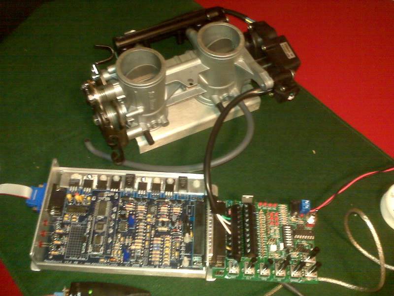
One of the first things I had to do was some wire mods on the ECU board. By default, the stepper feature is not physically connected on MegaSquirt. The output connections are left unconnected because they can be used for any of several options; stepper IAC is just one of the options. The mod itself is very simple, adding five jumper wires on the bottom of the board.

After lots of experimenting, I also had to perform another minor mod, bypassing some current limiting resistors that are built in to protect the circuit board and wiring from shorts. I guess I will have to just leave my shorts at home.

After that, it was just setting parameters, which was a very much experimental “try this and observe” process. I eventually arrived at some workable values.

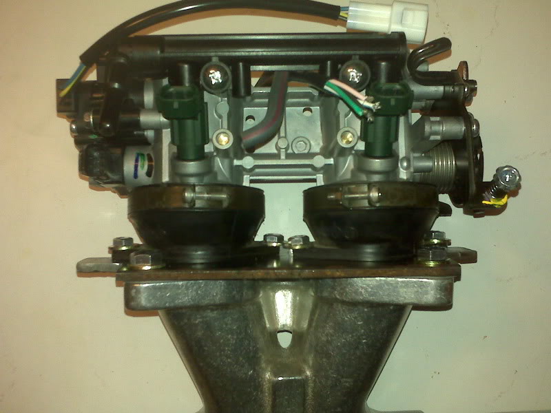
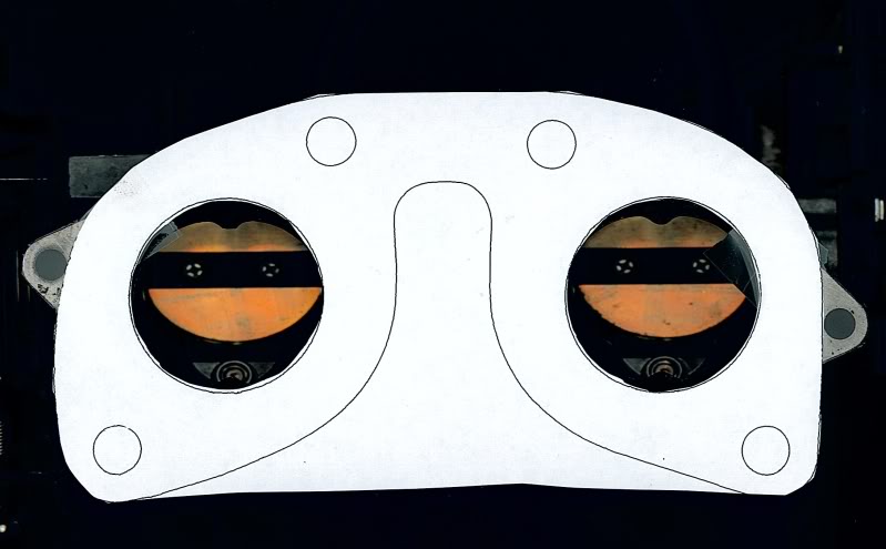
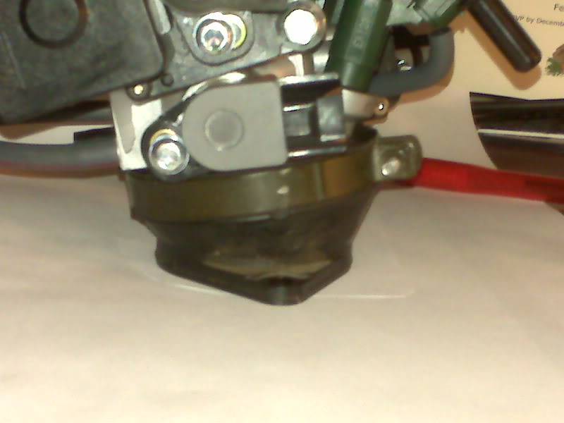
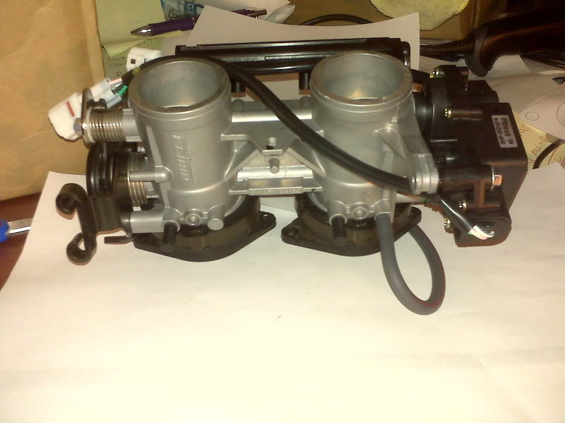
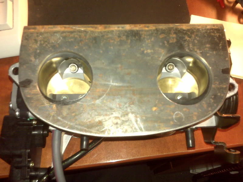
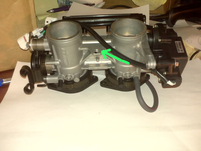
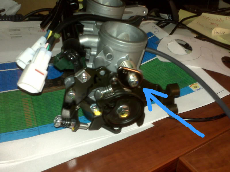
One thing to keep in mind is that my throttle body in it’s original Ninja 650 form uses a stepper motor to operate sub-throttles, but there is also a cam on the end of that shaft that operates the main throttle butterfly to provide fast idle. As I discovered experimentally, the subthrottle is completely open when the cam is operating the main throttle as far as it can. The subthrottle is at about 60% open when the cam disengages the main throttle completely. Although the partially closed subthrottle is not expected to affect normal engine operation until the main throttle is more than 60% open (and maybe not even then), I will probably remove the butterflies anyway.

One thing that I found confusing is that I was erroneously thinking in kind of “absolute position” terms. At power up, the ECU moves the IAC 350 steps (Start Value) to ensure it is open all the way. I thought of that as position 350, thinking that the system would then want to close the IAC down to 0 as the engine warms up.

I was wrong.

The two main states of the IAC, power-up and operation, are relative to one another. At power up, the ECU will use the Start Value to open IAC all the way with, in this case, 350 steps in one direction. Once the power-up routine is finished, that position becomes 0 and all temperature points are expressed as steps in the other direction from there. In my case, it then takes 145 steps in the other direction to completely close the IAC, or more precisely, to completely disengage the fast idle cam from the main throttle. It is 0 and 145 that are needed to generate the IAC Steps curve.

The other major value arrived at experimentally is the Time Step Size, basically the time between stepper pulses. The smaller the time, the quicker the motor moves, at least up to a point. I found that it seems reliable at 0.5 mS, which is way down from the default of 2.5 mS. I decided to give it a little margin and set it at 0.7 mS. It moves quickly, smoothly and quietly there.

For the entertainment value, at 5.0 mS, it sounds like an old 5-1/4″ floppy disk drive and at 10 mS, it sounds like a blender stuck on a piece of ice.

Sorry for the poor focus, but here is a bit of Blackberry video of it working.

Finally, it seems that operating the motor in the ‘Always On’ mode, where voltage is left on the motor to keep it stationary, makes the motor and driver chip run pretty hot. That mode is not really needed here, so I am running it in ‘Moving Only’ mode, which only sends power to the motor to effect an actual position change.

So, to summarize, it took me about 5 hours to make MegaSquirt open and close a little motor, but I think it still counts as a big step!

Decembre Loco

I’m sure I wasn’t the only one with a crazy month. It’s been go go go go go. I think the last of it is done.

Well, except for the weather… Expecting a bit of snow tomorrow, though it’s not expected to be much nor to stick around.

Santa thought organizing my tools might help me be good for next year, so he brought me a big rolling tool chest/organizer. I loves me some Santa. Lucky for me, Santa’s pretty cute, too.

Now that I’m not spending every evening getting the house ready for guests or shopping or whatever, I should FINALLY be able to start playing.

Driveway cleaning

Today was very nice and, difficult though it was to do so, we worked on stuff around the house instead of going for a ride.

Filled the back of my truck with trash and other discardables from the carport. I still had the boxes that various Harbor Freight items came in, such as the air compressor, engine stand, welding cart, tool box cart and soda blaster. Most were at least wrinkled from humidity, if not completely warped from rain. Fall leaves, countless shopping bags (mostly from AutoZone, which is probably a hint that I should be a stockholder) and no shortage of used paper towels littered the area.

We had some aluminum frame windows that were promised to our neighbor long ago. They were stored quite literally as far back in the carport as possible. Because of the work today, I was able to clear a path all the way back there and retrieve them for him. Tiny karma gain.

I worked from about 10:30A or so until 7:00PM. If you look at it critically from a before and after point of view, all I did was make room for one more trike. More importantly, though, 2/3 of the space is clean enough to easily roll things around. Another good evening’s work and I may be able to roll the purple trike all the way back where the best work space is and work on it at home for a while.

So long as it’s not devastatingly cold or actively precipitating, the space isn’t too bad. I have a 30,000 BTU heater almost exactly like this one and it keeps a decent working area warm. I may try to cover the gap between the top of the fence and the roof of the carport to keep some of that heat enclosed.

Trike is home for a few days

I have been essentially storing the trike at the BTW clubhouse. The *intent* was to have it down there to work on it, but mundane life has ensured that I have had little time to pack up and head down there, compounded by the need to keep my footprint there at a minimum for the holidays. Now that our (probably) final holiday shindig there has concluded, perhaps I can make some progress working on it down there.

But first, I want to get some stuff done that is arguably easier to do at home, such as the welding I need to do to complete the adapter plate.

An acquaintance is building an airplane from a kit and whilst perusing the builder’s guide on their website, I stumbled upon a piece of advice that I had inadvertently ignored: “[your construction space] should be as close to home as possible. Driving any distance at all to work on the [airplane, trike, whatever] will drive the time to build up by unimaginable amounts. One [airplane kit] builder estimated that having to drive only four miles to work on his project doubled his construction time.”

It also says that “Good light, air conditioning or heat as the climate requires, good ventilation and good organization are essential. An uncomfortable place to work means hurried, often poor, work.”

In my case, those are almost exclusive of one another. The clubhouse is a fairly well lighted space that has a roof over it, a decent amount of work space and a few specialty tools that are absent at home. It is, however, 4-5 miles from home.

My driveway is covered but otherwise essentially outdoors, and crowded with stored tools and vehicles. It is, however, very close to home.

Last edited by Sluggy on Fri Mar 19, 2010 12:08 pm, edited 1 time in total.

Intake Boots Arrive

Boots arrived today. As expected, I will need to remake or possibly just rework my intake adapter plate.

I trimmed the adapter plate I made a few days ago along the lines of the gasket to cleanly fit the manifold.

The boots, however, have mounting tangs that overhang an area that was cut away. My first thought is that I should cut a new plate, but I think I may end up time ahead by simply welding on the two “wings” needed for proper attachment.

I remembered from looking at a Versys at the IMS that the boots mounted such that the TB was presented to the engine at a slight angle, but its shallower than I remembered. I don’t think it will make much, if any difference. Because of the direction the throttle cable will need to route, the TB should end up tilted towards the doghouse.

From the techie showoff standpoint, that will be cool because the injectors and injector wiring and plumbing showing is cool. If, however, the throttle cable will have to bend too sharply between the TB and the doghouse, I’ll have to turn the assembly around. Well, the clean side will still be pretty cool.

I definitely want to salvage this adapter plate. I don’t think I could have matched the diameter and spacing of the holes any better! Still needs deburring, but the match up very nicely.

I think I will try to drill and tap holes for the boots and choose cap scres of the appropriate length to not protrude a lot on the gasket side of the adapter plate. They will just miss (or just nick) the gasket, so they will also probably just miss (or just nick) the casting on the manifold. Because the boot seals with an O-ring, I don’t imagine I will need 120 ft-lbs of torque to hold them down.

I want to run a brace between the adapter plate and a mounting tab at the top of the TB. This may end up being a bracket formed from some nice flat I have or maybe even just a long bolt.

On this TB, the stepper motor driven subthrottle shaft includes a cam that operates the throttle for fast idle.

MegaSquirt does not at this time support subthrottles, but it should be a simple matter to remove the subthrottle plates and use that motor for my idle air control.

Lastly, for this update anyway, I have yet to find any authoritative information on the flow rate for these injectors. I may try to work with it assuming that they are between 200 and 250 cc/min. If that doesn’t work out, I suppose I can rob a couple of the known 245 cc/min injectors off Buzz.