Category Archives: 70-something Stires Trike

Prepare to be shocked…

The tank is finished!

I stopped at the hardware store and bought both oxygen cylinders they had. Ran them both out, too, though when the second ran out I was only reflowing some of the brazed joints for appearance’s sake.

It’s not my most beautiful brazing job, but I’m confident it won’t leak. Between the cylinders running out and me pausing to fetch fresh rods, etc, the bronze flowed a little wild in places, but it’s functional and will be covered in paint, anyway :)

I had to drill out the fuel pump mounting holes to account for slightly misaligned mounting bolts, but it didn’t take much to mount the pump. I even verified that it spins!

I wire brushed the filler spout, drilled out the mounting holes, cut a gasket and bolted it in place. In pressurizing the tank with a little air, the only leak I can detect is around the filler spout. It is cast from aluminum the sealing surface isn’t really flat. I worked it over with a file and it’s much better, but still leaks a little air. I will apply a little gasket sealant and that should take care of that.

I put a valve and a very short hose on the old fuel tank outlet and will use it as a drain.

All that’s left is to sand, paint and install it.

Oxygen everywhere but in the bottle

Man, I’m getting tired of running out of oxygen with my little Bernzomatic torch pretty much any time I start a project. I have a real torch and a couple of rusty old bottles. I need to see if I can get them filled and get/build a cart for the cylinders. Until then….

The fill spout on the tank is currently an aluminum flange that was “sealed” with PC7 or Bondo or some such applied inappropriately and secured with 4 sheet metal screws, which obviously leaked. While I want to someday replace it with a nice remote filler, for now I just want to fix this one. To that end, while the bottom was still open, I drilled out the sheet metal screw holes and brazed four 5mm bolts from the inside, providing both a strong method of attaching the spout and a reliable seal. I will need to clean off the sealing surface of the spout, drill out the mounting holes and cut a gasket for it.

Once I was done with the spout bolts, I cleaned the interior surfaces of the tank with WD40 and steel wool and wiped it out. It looks much better and hopefully the layer of WD40 will minimize the formation of new surface rust before I fill it up.

I wanted to put the bottom in from inside so that the remaining rim from the cut out bottom will serve as a strong bond so that the brazed seam will not be under a lot of mechanical stress. I trimmed the bottom for a snug fit. Starting with the end closest to the fuel pump opening, I used a deep C-clamp to secure the corner and tacked it in with a small bead of bronze.

As eluded to earlier, I ran out of oxygen after getting about 6 inches of either side of the first corner. I tried to use the MAPP gas with an atmospheric torch to continue, but it just doesn’t get it hot enough, at least not something this big.

I still wanted to continue for a while, so I decided to tack weld the rest of the bottom. With clever application of the C-clamp, Vice-Grips and a pipe inserted through the filler hole, I was able to tack all the way around the rest of the bottom. If I was better at welding, I would prefer to weld around the whole thing, but historically, I have had trouble getting a seal with my welding :) In any case, it will be ready for brazing when I get more oxygen tomorrow.

Bottoms Up!

I cut out the old bottom of fuel tank and made a new one.

The new bottom has reinforcement inside the bottom of the tank. I made it from two strips of 2″ x 1/8″ mild steel. Each side has half the opening cut from it and is firmly stitch welded to 16ga sheet metal bottom. I welded the seam between the two places with them in place so that there would be a little extra penetration into the bottom. The welds were not pretty, but they appear to be solid. I think I had the wire speed slightly too slow, making it sputter a bit

I drilled and placed the bolts and welded the heads to the reinforcement plate then flowed solder around the bolts to seal them.

Remaining to be done is cleaning the inside of the tank of mostly light surface rust and installing the new bottom. I have not yet decided whether I will try to attach it from the inside of the tank, which will be stronger and arguably easier to seal, or the outside, which will probably be easier overall to do.

Fuel Tank Work Second Thoughts…

I tacked, welded and dressed a reinforcement ring for the fuel pump. I think I really should have used a thicker piece, but since I’ll probably have to replace the whole bottom of tank anyway, we’ll see if this will work.

Using friction from the gasket to hold the bolts, it was a pretty simple matter to bolt it in place.

Of course, now that I think about it, it’s going to leak like a sieve unless I seal around the bolt heads. Even then, it will leak around the bolts between the tank and the reinforcing ring because the ring is only welded on the outside edge. Besides, there are probably pinholes in that weld.

Soooo… I guess I wasted an evening. Except that I just needed to do something with my hands.

I think I will need to get a 3 inch holesaw and a piece of 1/8″ or 3/16″ plate slightly smaller than the bottom of the tank. Cut the hole, drill for the fuel pump bolts, braze them from the inside for studs, secure the plate physically to the tank with a few bolts and braze around outside edge to seal it.

Somewhere in there, I need clean all the rust chips out of the tank out, too.

Delay for EDIS, but work continues…

Drat.

Boost Engineering has essentially backordered the trigger wheel, citing a manufacturing problem that should be corrected shortly, hopefully by mid April. Since I don’t want to further delay running the engine, I will get it running with the 009 distributor and convert to EDIS later, though hopefully not much later!

In looking for something unrelated, I found a cache of missing parts, namely the bag-o-relays and relay sockets.

Once I get the fuel tank in order, I should be mere hours from trying to start the engine.

Fuel Tank Work

After the last part of the week was stolen from me for work and the weekend and Monday fell to a stomach virus, I was definitely ready to cut some metal.

I pulled the fuel tank off the frame and drained it. I’m wondering why I completely filled it way back when. Now I have a really full 5 gallon can full of iffy gas. That’s a lot of mowing.

I first pulled the filler neck off. I found, not entirely to my surprise, that it was held by four sheetmetal screws and “sealed” with what appears to be Bondo.

With the filler neck off, I could photograph inside the tank. It’s not a happy sight. The outside of the bottom is somewhat pitted as well. Since it’s only about 16ga steel, there’s not a lot of material to corrode away. The entire bottom, if not the whole tank, should be replaced.

While I am formulating plan B to replace the bottom plate (or the whole tank), I will continue with plan A.

I marked and cut the hole for the pump and test fit it. I also cut a trial gasket.

Its Always Something…

Well, ok, it’s not so bad as that…

I cut new intake gaskets, installed the new intake boots (minus the clamps; I have learned to wait until I’m sure I’m through for those), bolted on the end castings, installed the manifold and trimmed the adapter plate as required to clear the alternator. Then I found an unexpected problem.

The throttle body must be mounted so that the throttle cable faces rearward. Between the throttle bracket and subthrottle motor, it simply wont clear the doghouse facing it. The other way, however, the inlet to the fuel rail wont clear the doghouse. I’m not terribly excited about having a plastic part carrying gasoline at 43.5 PSI crunched up against a vibrating metal part.

All is not lost. It turns out that the fuel rail fitting is a separate part from the rail, secured with a rather heavy screw and sealed with an O-ring.

By removing this screw, rotating the fitting and clamping the fitting down with a new fabricated clamp, I can adjust it to clear. The rail can be installed with the fitting at either end. I tried a couple different ways and have thought of a couple more, so I haven’t decided exactly how I will configure it, but it shouldn’t be too big an issue.

Otherwise, the 99% final configuration looks pretty good!

A Small Dose of Disassembly and a Big Dose of Ignition

I pulled off the old manifold (and, of course, the alternator) from the engine last night and verified some of the fit requirements. While I was in the pulling mood, I also pulled the distributor. There was quite a bit of corrosion around the distributor shaft. I suspect there may have been blasting soda left on the surface that, once it got wet, dissolved the protective coat of oil. In any case, it took substantial effort to pull out the distributor, but there appears to be no permanent damage.

The case stud that the manifold normally mounts to was missing. I recall before discovering that the threads are pretty bad in that case half. I spent a few minutes chasing the threads with a tap and installed a stud which should arguably have been there all along.

I painted the new manifold to match the rest of the engine. Once the EDIS system is in place, I will paint the oil pump block plate and the distributor plug to match.

Speaking of distributor plug, after a brief search, I found an online source [Boost Engineering, since closed] for one, as well as a ready to use trigger wheel/crank pulley.

I have several stock pulleys and a DIY AutoTune trigger wheel.

My plan was to mount the trigger wheel to a stock pulley, with spacers to lift it out from the surface. Since the center hole of the trigger wheel is too small for the head of the bolt and I don’t currently have an appropriate way to enlarge it, I would need to make it removable for access the the crank pulley bolt. Furthermore, I would need to carefully place the wheel very close to the precise angle in relationship with TDC and allow for both radial and angular adjustment of the pickup.

Well, this pulley fixes all those problems at once. It’s not particularly cheap at $135, but it’s a far more elegant solution than what I could make at home. The trigger ring is continuously adjustable, leaving me to be concerned primarily with radial adjustment of the pickup. I’m basically trading dollars for convenience and work time.

Similarly, while I could definitely have someone turn a distributor plug for me or even do my own with my drill press, this one will be here in a couple of days and I’m not sure I could have one made for the same money.

BTW, Boost Engineering [since closed ] also sells complete kits of either MegaJolt ignition only systems or MegaSquirt systems with all the ignition components (no EFI parts). Since I had most of my system components already, I didn’t need the whole shebang, but it’s cool to see someone offering it.

Harness Wiring

It took most of the day, but I wired the throttle body and reconfigured my original MegaSquirt ECU harness.

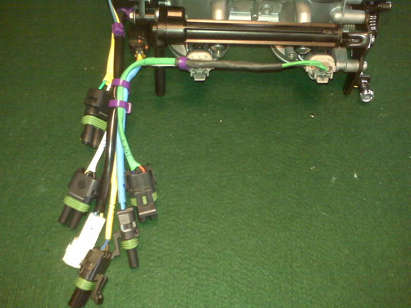
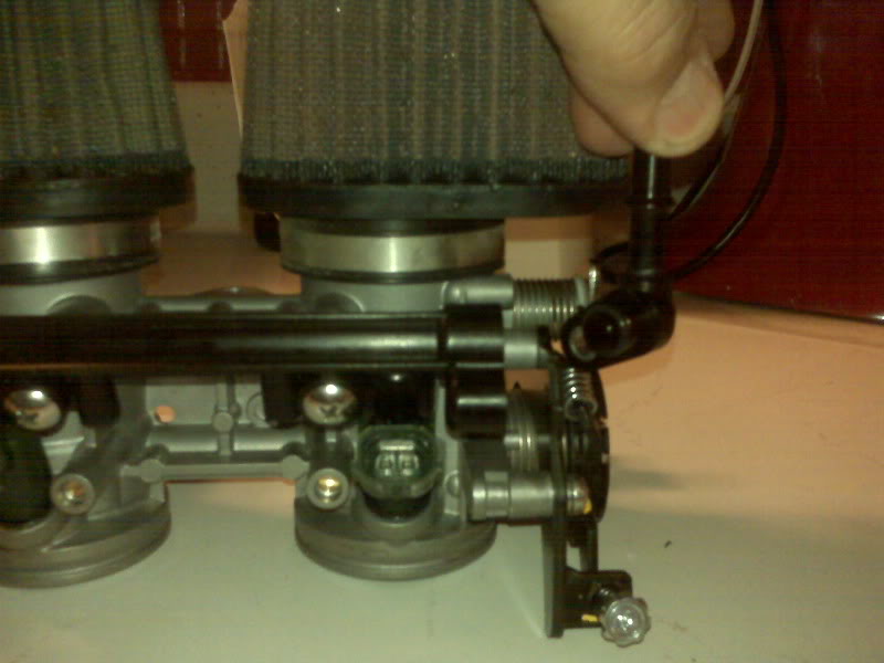
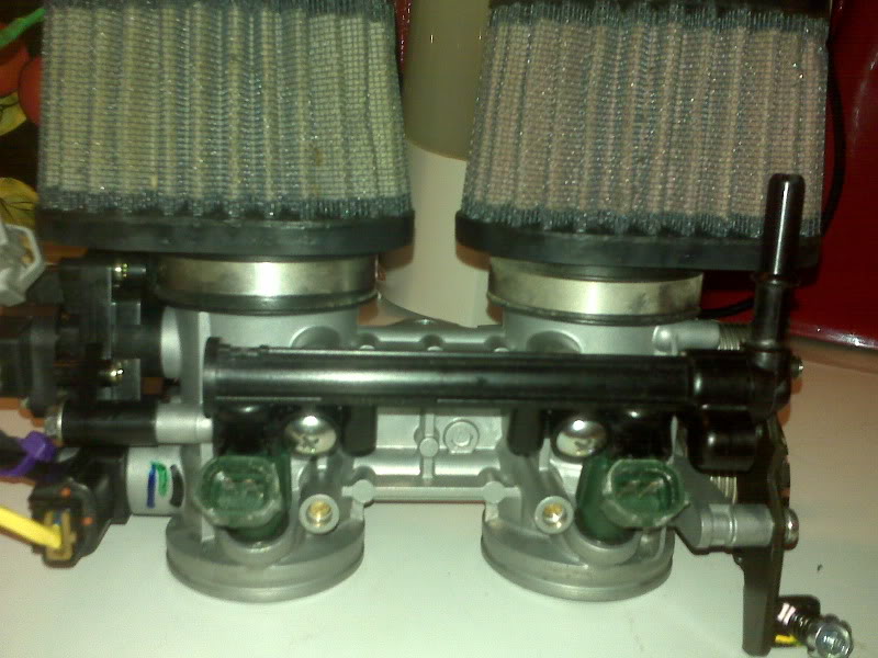
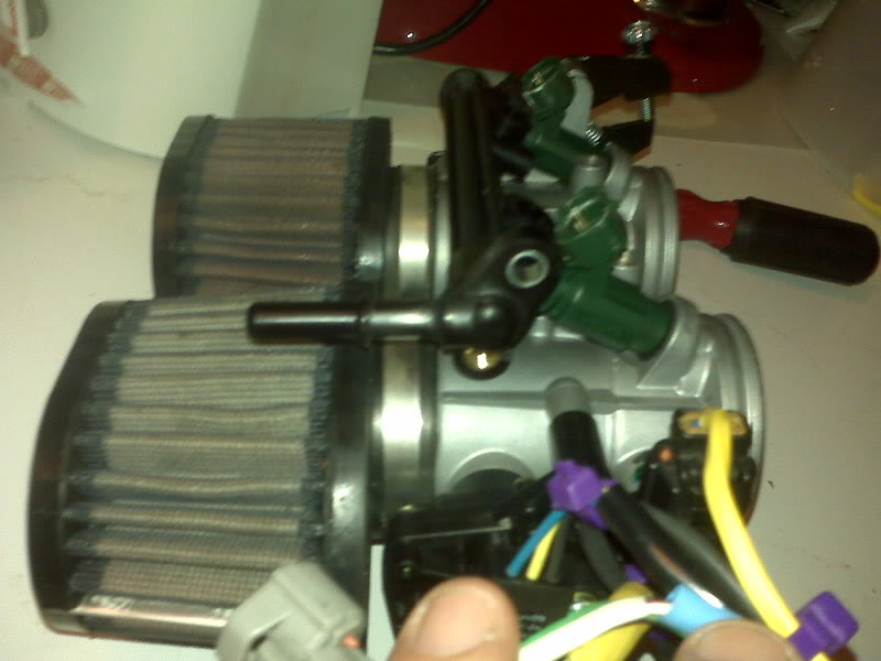
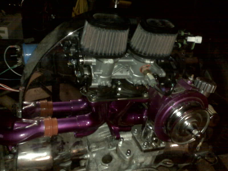
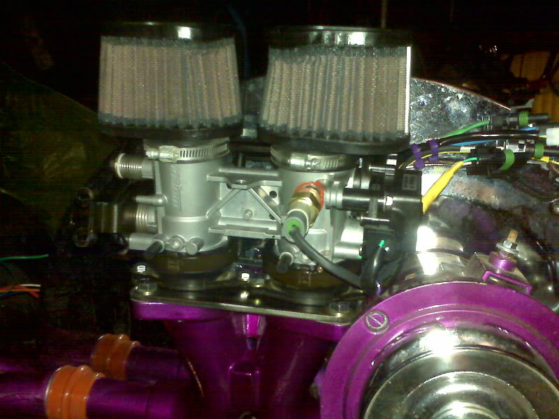
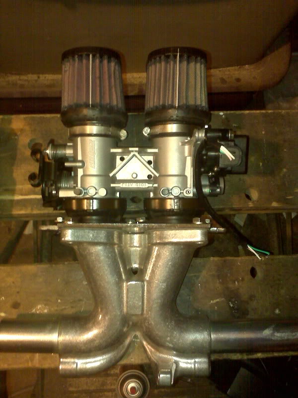
For the throttle body, I took the shortest two connectors from Buzz’s old harness and remade them, connecting one injector to each output and running separate power leads. When I originally made the old harness, I was not really aware of the needed seals. It doesn’t do much good to have a weatherproof connector without sealing around the wires. So even though the throttle position sensor (TPS) cable was a suitable length, I needed to cut the pins off anyway, so I rewrapped it in yellow heatshrink while I was at it. Astute observers will see an extra cable in the bundle, the one with the white connector. This is the currently unused factory subthrottle position sensor. It costs nothing to leave it there, just in case someone someday writes subthrottle support into MegaSquirt :)

On Buzz’s harness, the intake air temp (IAT) wiring was sort of an afterthought, so while the sensor was on the throttle body, it was connected through the frame harness. This time, it’s right there with the other throttle body connectors. Also, the old IAT and coolant temperature (CLT) were wired to the ECU in a 3 pin connector that shared grounds because those sensors both came in from the frame harness. In this case, one is on the TB harness and the other will be on the engine harness, so they will each have a two pin connector.

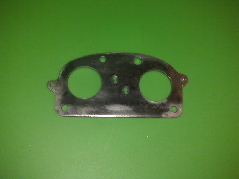
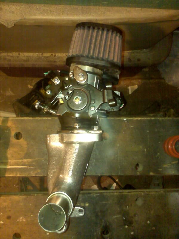
New to this lineup is the wiring for the idle air control (IAC) stepper motor. This was one of the modifications needed inside the shell, adding four wires. The pins are essentially randomly connected to the motor itself. Unless I was just EXTREMELY lucky, I will need to rearrange the pins before I can expect the motor to work.

While I had the DB37 shell open, I also made the injector leads into single 14ga wires instead of doubled 18ga.

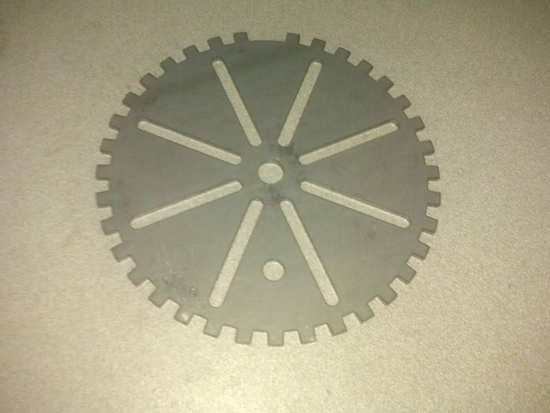
As for the harness, it’s mostly like it was, except nicer. Some groups of wires are bundled together with expandable sleeving and all connectors have been remade with seals. Finally, connectors were added for the options applicable to this job that weren’t on Buzz, like the EDIS ignition system and a permanently connected wideband exhaust oxygen sensor.

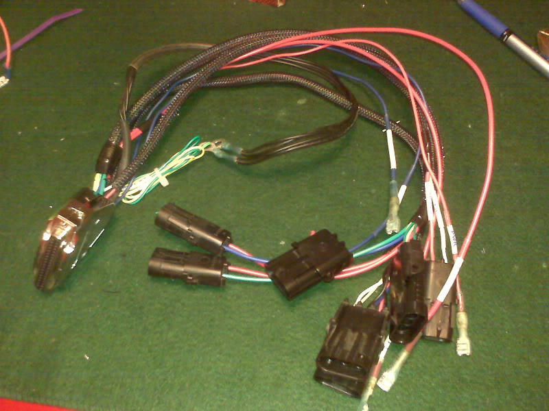
In the old system, the wire labeling was very clear until the wires were handled. Wherever possible, I have relabeled the wires using white heatshrink tubing, written on with fine point Sharpie then covered with clear heatshrink. As I re-redo a couple of the connectors, I will relabel the lines I missed.

More Intake Progress

I have the throttle body adapted to the manifold in what I presume is very nearly final form.

The 95% completed adapter plate is the key to making this very nearly a bolt on conversion.

Sharp observers will see that I drilled the two inside holes incorrectly the first time. I had my template placed wrong. Luckily, there was still plenty of metal to thread into, though running the tap though was tricky. I had to run it forward all the way through and pull the shank of the tap though the back side of the hole. Attempting to turn it out backward made the tap cam into the erroneous hole and jam.

To truly finish the plate, I need to weld on a brace fro the throttle body, media blast the entire assembly and paint it with something fuel-proof, probably epoxy.

As a side note especially for anyone wanting to use this throttle body, get the stock mounting boots and O-rings. In my opinion, scratch fabricating something to fit is just not worth the effort. They are about $20 apiece from Kawasaki [part no 16065-0024]; I paid $20 for the pair on eBay. One online Kawasaki parts house sells the O-ring for $4.71 each, but I found an excellent equivalent O-ring at AutoZone for $0.99 each, FelPro part number 35087. It happens to be for the water outlet for a 91-95 Saturn 1.9L. Beware, however, my AutoZones tend to stock only one per store, so I had to go to two stores.

As for the rest of the intake manifold assembly, I have not placed it on the trike yet, but I have mocked it up in the level mounting position to see what the angle of the all components will be. As luck would have it, the rearward angle of the manifold and the rearward angle of mounting boots are the same, or at least close enough that I can’t tell. It remains to be seen whether I will have the throttle bodies mounted as shown or flipped around so the throttle cable approaches from the front.