Interesting to get the update at 11:33PM, but I’m still happy about it!
All posts by admin
Header Rework, Stinger, Bits and Pieces
Rather than completely duplicate the posting, I will simply refer you to this blog entry for the details of reworking the header.
In the intervening 5 days since that work was done, I’ve had little chance to work on anything before tonight.
On the engine/exhaust, I bolted on the header and carefully but temporarily placed the bumper to check for clearances, such as the O2 sensor. It clears nicely! If you are interested, you can refer to today’s blog post for more details about the bumper and other non-engine things.
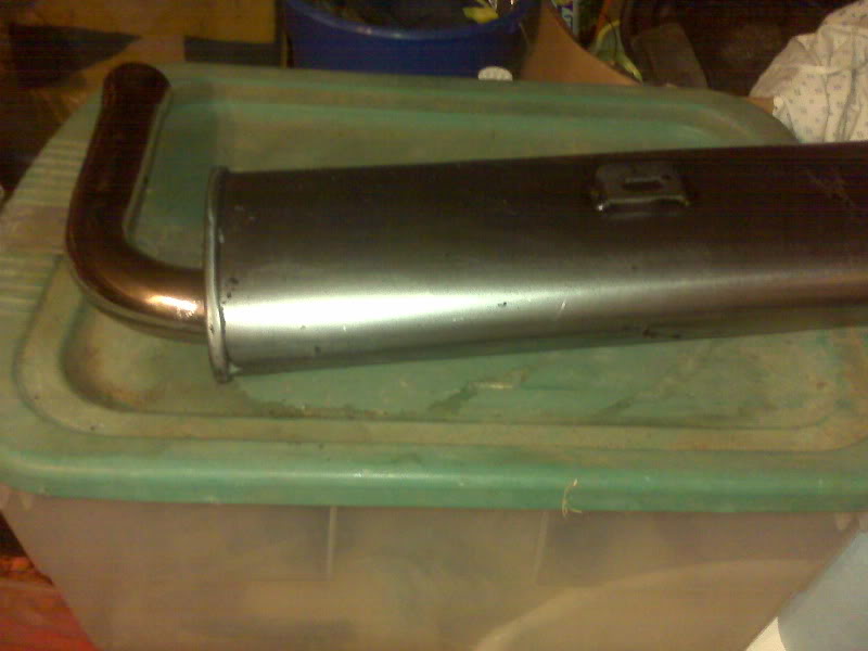
I got the chrome stinger and baffle on the way home from work. It seems almost silly to pay $40 for what is essentially a slightly flared pipe with a flange, but I couldn’t make one anywhere as quickly as I picked one up. It is the swivel type and bolted on nicely, though I didn’t cinch it down permanently. I will need to remove it to drill the stinger and baffle for a retaining bolt. Sadly, this counts as the best picture I took of it. I will take a better one in the daylight and replace it.
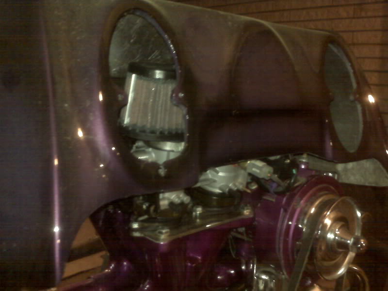
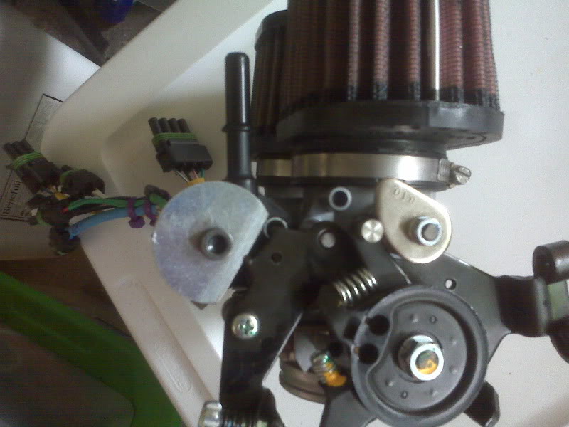
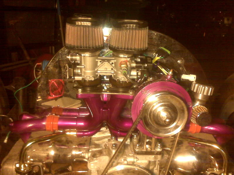
I needed to see how the body cleared the bumper (it does) and while the body was down out of the rafters, I also verified that the throttle body and air filters will clear the body. Looks like it was designed around it!
In other stuff, I put on the intake boot clamps and the heat riser tubes.
I’d hoped to work on the fuel tank tonight, but ran out of time. The liner is well cured by now…
Still here
I’ve been busy with helping my mother-in-law move, so there hasn’t been any active work on the engine, but I do have a note that my trigger wheel will be shipped, hopefully as early as tomorrow!
What Fits and What Doesn’t
Header and bumper in the former, muffler in the latter…
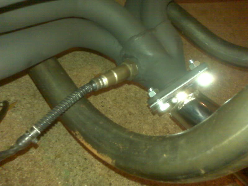
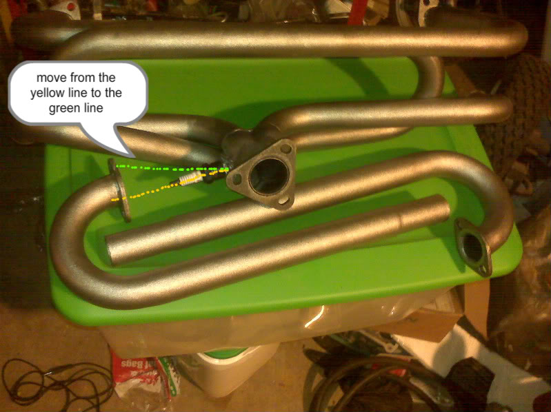
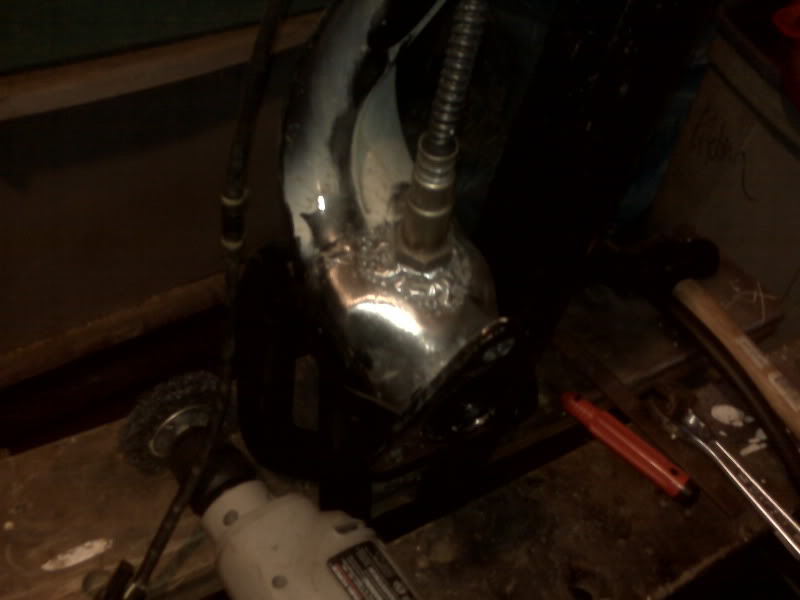
No good deed goes unpunished. While waiting for my baja bumper to arrive, I insisted on staying busy and moving the project forward. I welded in a bung for the O2 sensor and handed the header off to a buddy to run through his shot peen machine. The muffler did not go through the machine, so on Friday I sprayed it with chemical paint stripper, which worked quite well. On Saturday, it was wet and yucky out, but I still managed to get a couple of things done on the trike, such as mocking up the bumper to see how it would fit and temporarily bolting on the header to see how it would clear.
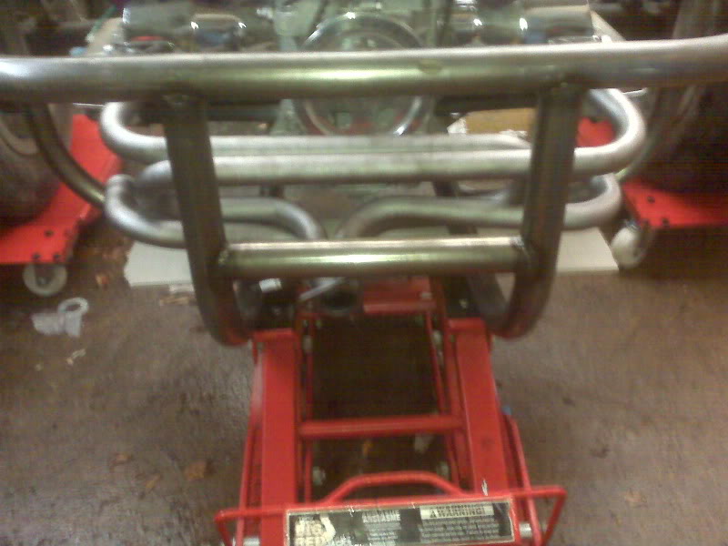
Well, the header clears.
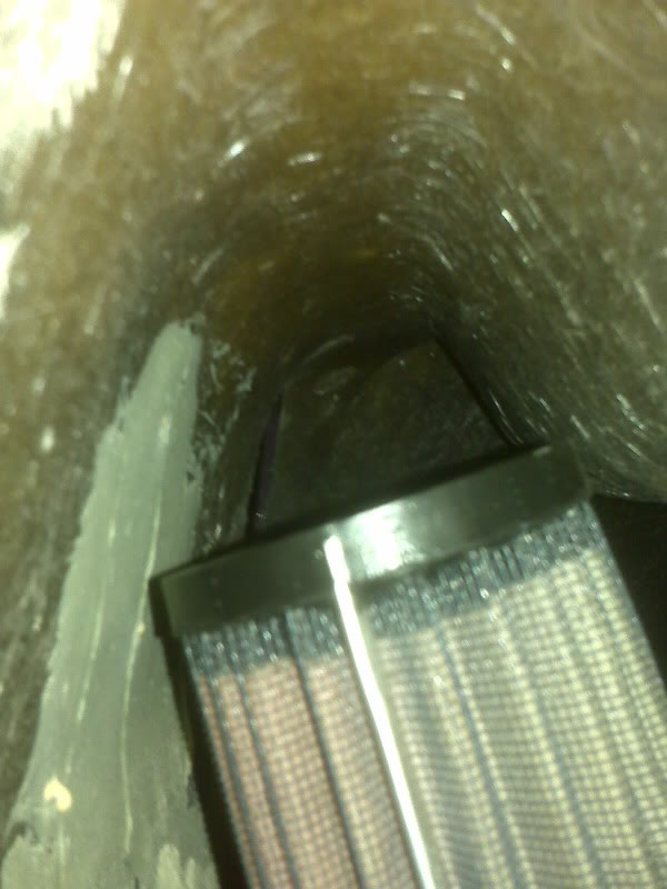
The O2 sensor and the muffler don’t.
From the pic, you can see that the spark plug hits the bumper. The O2 sensor is even longer and has wiring attached, so it definitely won’t clear. Moving the bumper downward might clear the sensor, but would not look right and probably wouldn’t work with the bumper’s top mount. Conequently, the sensor needs to move.
While I hate to weld in (or probably braze in this time) another bung and plug the first one, it won’t be very difficult. Another option, however, might be to heat the metal around the bung and lever upward on the plug, making it more parallel to the ground, rather than pointing slightly downward. This may clear the bumper and my planned receiver hitch.
As for the muffler, I don’t really like a stinger that much, largely because you have to remember to cover it in the rain to keep water from being funnelled directly into the engine, but they look and sound pretty good and it will fit and clear the bumper.
Perhaps in the future, I can get a muffler shop to bend up a pipe for me, maybe something like this.
The fuel tank is curing well. Only two or three more days to go….
Tank Liner and Exhaust
The tank liner stuff went well. It is silvery with what I presume are aluminum particles. Now begins the waiting as it cures for 4 days.
I got the exhaust back from the peen blaster. As expected, it has given the surface a little texture. The sparkplug left in as a thread protector appears untouched. Bizarre.
The muffler was not run through the machine; the operator was concerned that it might not survive the ordeal. I picked up a can of paint stripper and it has worked really well. I need to do some touch up removal and clean the residue off and it will be ready to paint.

Trike ADD
It’s not so much attention deficit disorder as it is lots of little things needed attention and several related issues all had updates today.
The bumper arrived. I didn’t realize that it would arrive without a box, though perhaps obviously, it would have been a monstrous box.
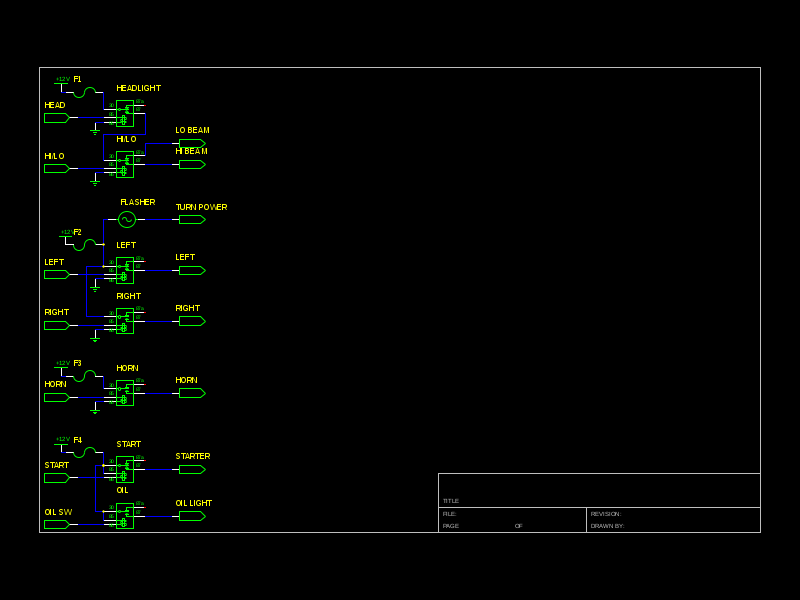
In some bits of spare time here and there, I have been working on the wiring diagram. Love open source software. This is about the third start of the diagram, but I have my head on straighter this time. ![]() The parts library did not have a Bosch relay, but I copied a similar relay and relabeled the pin numbers.
The parts library did not have a Bosch relay, but I copied a similar relay and relabeled the pin numbers.
The exhaust system should be shotblasted bare by now, except for the muffler. The operators were concerned that the relatively lightweight metal on the muffler might not survive the Wheelabrator machine’s aggressive cleaning, so I will need to remove the paint on it another way, probably chemically.
I started the application of the POR-15 fuel tank repair product to seal and refurbish the fuel tank. This is basically a three step chemical process.
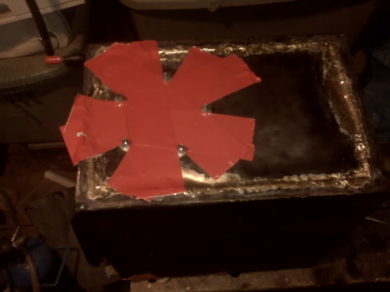
First, the inside of the tank is cleaned of fuel, grease, varnish with a powerful non-petroleum degreaser they call Marine Clean. That is mixed 1:1 with hot water and poured into the tank. The directions suggest sealing the holes in the tank with duct tape, which I did, in red because that’s what was nearby. The cleaner is sloshed around thoroughly; I turned the tank on each side and agitated for 5 minutes, probably overkill. The Marine Clean is then rinsed out very thoroughly with water. I propped the tank up off the ground, stuck a sprayer hose in the top of the tank and let the water run for 5 minutes, flipped the tank over and let the water run another 5 minutes from that side.
Next, the insides are treated with Metal Ready, a phosphoric acid etchant that will make the final coat stick extremely well. Each side needs to soak in it for 20 minutes, so I basically set the tank on one side, poured in enough to comfortably cover that side and set my phone alarm for 10 minutes.
I again sealed the openings with duct tape. When the alarm would go off, I would agitate it and hit snooze. You can reset the snooze apparently indefinitely, which is handy. When the snooze expired, hit snooze again, agitate and turn it to the next unsoaked side. I kept alternating between agitate and turn until all 6 sides had been soaked. I drained the Metal Ready into a plastic bucket then did the same 10 minute rinse as I had for the cleaner.
For the next step, the inside of the tank needs to be completely and absolutely dry. I don’t have a handy blow dryer to leave running in the thing, but I did set up my shop fan blowing through it and am leaving that overnight. If that doesn’t do it, I will set it in front of the big heater for a while tomorrow.
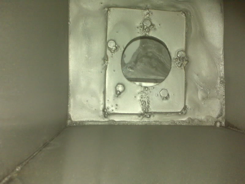
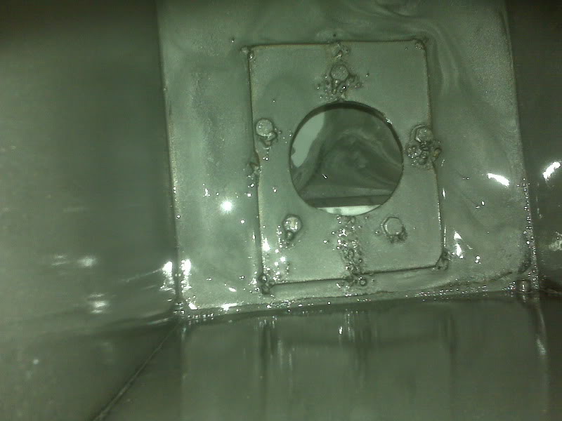
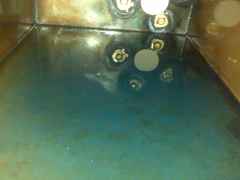
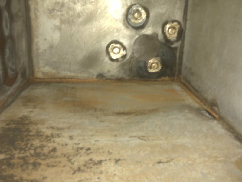
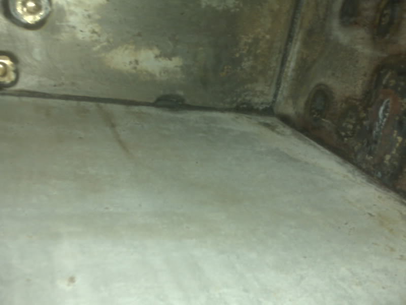
[update from Friday: The fan running overnight seems to have dried the tank just fine. Take a look at the inside!]
Once it’s dry, seal up one opening, pour in a gob of Tank Sealer, seal up the other opening and basically slosh the stuff around until you’re good and tired of it and let it drain for 30 minutes to ensure it’s not puddled. It then needs to cure for 96 hours (that’s 4 days, kids) before fuel is put in it. The waiting is the hardest part ![]()
During the 20 minute soaks above, I was not idle.
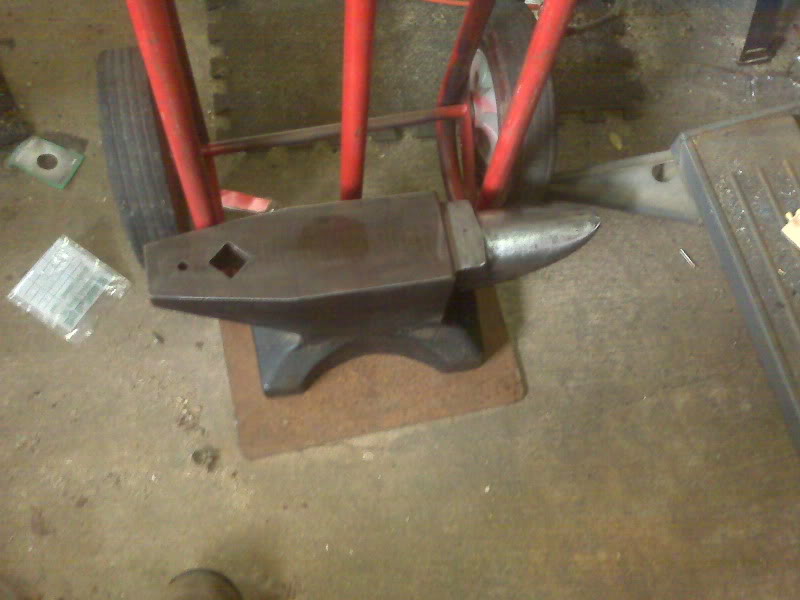
A friend with plans to demonstrate metalworking at a Boy Scout function needed to come to borrow my anvil, which is about 1/3 the weight of his and is thus MUCH more portable. Before he arrived, I cleaned up the anvil and got it ready to load.
While I was waiting for Bill, I partly refurbished the original headlight for the trike. It will be serviceable.
Speaking of headlights, I ordered a cheap HID conversion for an H4 headlight. I need to find a suitable reflector that will fit this trike. In doing the headlight refurb above, I neglected to measure the sealed beam, but if it is a standard 7″, securing a suitable reflector will be easy.
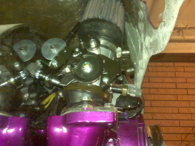
I also did the little mod needed for the fuel rail.
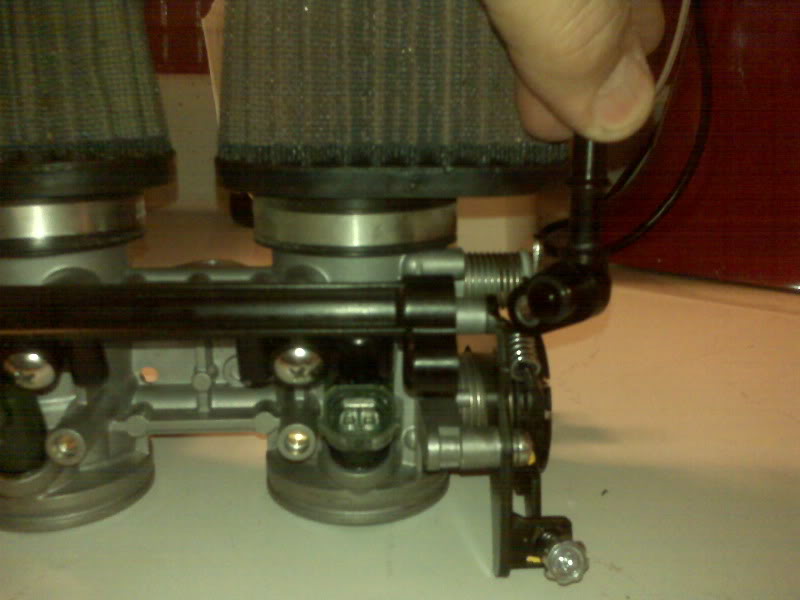
Basically, I had to shorten a spacer and cut a bit off the side of a fender washer so the parts would fit and now the washer retains the fuel rail fitting, which is now pointed in a useful direction.
As I was finishing that project up and monitoring the fuel tank etching, Bill arrived. We visited and I showed off the trikes and bikes that he hadn’t seen. We loaded up the anvil and stand and he headed off to procure more demo equipment.
After Bill left, I dug out the handlebars to determine how best to put on a bracket for the speedometer. I had forgotten that the handlebar is slightly bent. I spent more time trying to figure out how best to straighten it. I think I will need to borrow a rosebud to heat a large enough area of one bar to impart a slight twist to the metal, followed by another heating elsewhere for a slight bend, or straightening a slight bend, depending on your point of view. I will need to put the bars on the trike to really determine where to put the speedo bracket. I hope to do that tomorrow so I can get the bracket done and get the bars out for powder coating. I’d rather chrome them, and I may chrome them in the future, but for now, powder coating in much more cost effective for me.
Once the Metal Ready was out of the tank and it was rinsed and had the fan on it, I gathered up relays, sockets and connectors with the intent to go inside and start making the local relay interconnections that will be needed for the chassis wiring. After having a few chores to do, I decided to sit down and do this update instead of tearing into the relay wiring.
Oxygen Sensor
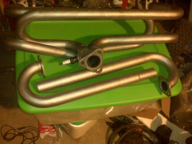
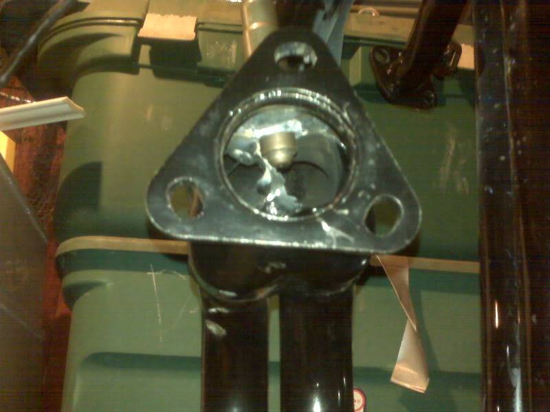
Putting the oxygen sensor bung in was not too tough. I did have one problem with a burn-through, then I had to pile on more material and to clean that up, it got pretty thick. I’m pretty sure it’s sealed, but it’s not particularly pretty.
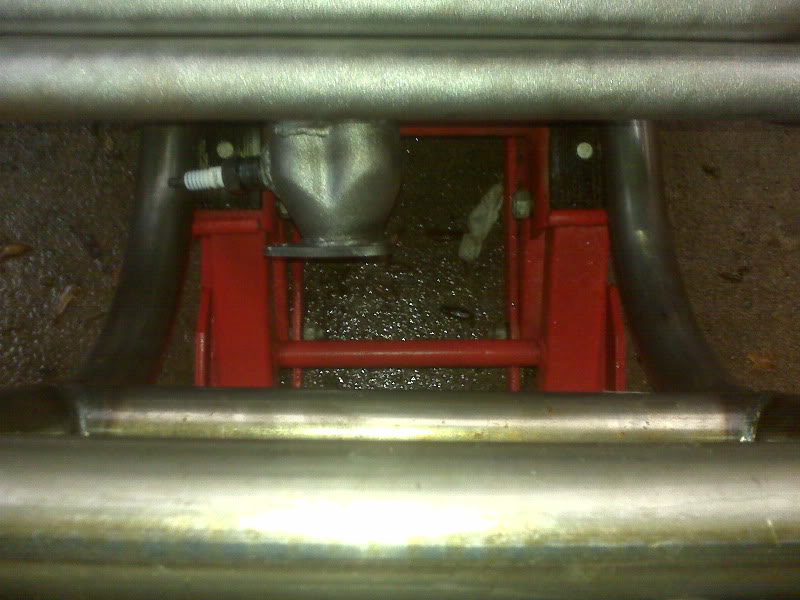
The sensor is placed on the left side of the collector. It is not exactly gases from all four cylinders impinge on it, but it sits directly between the pipes for cylinders 1 & 3.
I have plugged the bung with a suitable spark plug and after I get a piece of bike inner tube to cover the chrome bit of the muffler, I will deliver the system to someone who will shot peen all the paint off it. I can then paint it with a decent high heat paint like VHT Flameproof.
Throttle Cable, Switch Pod and Trigger Wheel
Although most of this update is about components that are not directly EFI related, they are still necessary for the engine to run, so I will post them here.
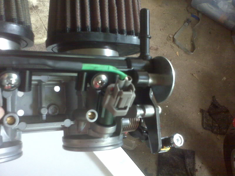
I opened the throttle cable package from Flanders. When I placed the order, I added a few extras and a few alternatives. I found that I had ordered the wrong size straight adjuster. It turns out ok because the configuration seems to work better without that particular type of adjuster anyway. The cable end for the throttle body is ever so slightly too large, but I’m sure I can make it work as well. Otherwise, it looks like the throttle cable should come together very well.
I also started working on the switch pod [Ed: link is to replacement for the now discontinued one I have, which has high beam pushbutton and kill switch, that I rewired to use for start switch] . As I learned from using the same model switch for the yellow trike, I can use the momentary ‘kill’ switch as a starter switch, but I need to make a modification. This switch pod is intended to help one convert an off-road bike to street legal. As supplied, the headlight switch shorts the kill leads when it is in the off position. It’s a simple matter to open up the pod and snip the brown/white wires between the kill switch and the headlight switch. This isolates the kill switch as a normally open momentary switch.
I also learned that this switch cannot handle the current for the VW starter solenoid and thus needs relay isolation. I intend to also isolate the headlight and horn wiring with relays. This will result in quite a lot of wire stretching from front to back, but experience has shown that it will be worth it.
The wire on the switch pod itself is too short to reach from the bar all the way under the body, so I will need to extend it. Likewise, the speedometer wiring is too short and will need to be extended. Both will need connectors, but the standard WeatherPack connectors I’ve been using are a bit bulky for what will turn out to be a dozen or so wires from each device.
I received the distributor plug yesterday. It appears very well made and ready to plug into the block. When I got the tracking info from Boost Engineering, I’d hoped that the entire order was enroute, but alas, it was only the plug. I emailed them to let them know I had received the plug and to check status on the trigger wheel. It is expected to ship early next week!
Exhaust Looks Great, Fuel Tank Does Not
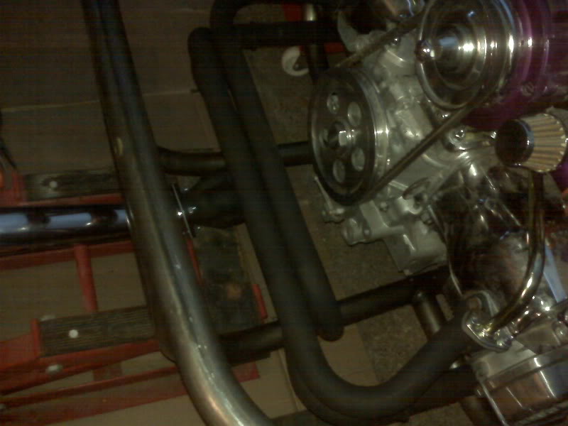
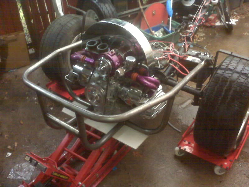
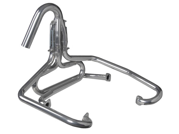
The exhaust is installed, albeit temporarily. It looks great! It mounts low and does not obscure all those pretty purple and chrome bits on the engine. ![]() I hope, however, that the baja bumper clears it.
I hope, however, that the baja bumper clears it.
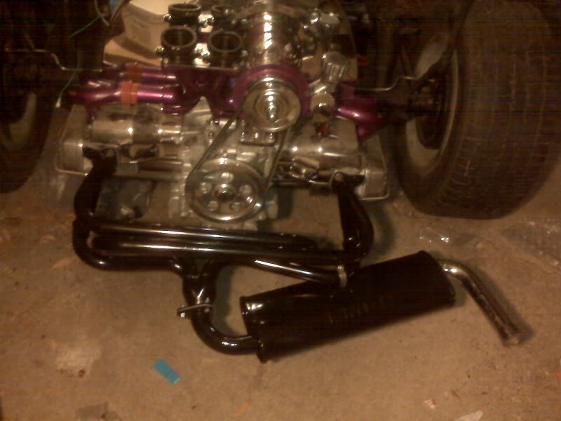
It’s temporarily mounted because I wanted to verify fit and take a couple of pictures. I’m very pleased with how it’s looking. As for the exhaust, before it is permanently installed, I need to strip to factory paint off it. The paint on it is plain ol’ paint intended to keep it from rusting on the boat. It is *not* high heat paint. While it’s bare, I will install the oxygen sensor bung, then repaint it with high heat paint. It’s too bad there doesn’t appear to be a purple high heat paint, at least none that I’ve found.
I also finished a few other things that were pending, like completing the installation of the alternator and putting the belt on.
While all that was going on, I set the fuel tank on a stand and put about an inch of gasoline in the bottom of it. It did not immediately appear to be leaking, but once I’d gone on and forgotten about it, I came back to see a fairly large puddle on the floor under it. ![]()
The entire bottom of the tank was wet, so I couldn’t really tell where it was coming from.
I used/tested the fuel pump to empty the tank and another day, I will lightly pressurize it with air and find the leak(s) with soap bubbles. Maybe I’ll be lucky and it will be around the pump, needing only a better gasket to fix. We’ll see.
I’m Exhausted…
Or, will be soon…
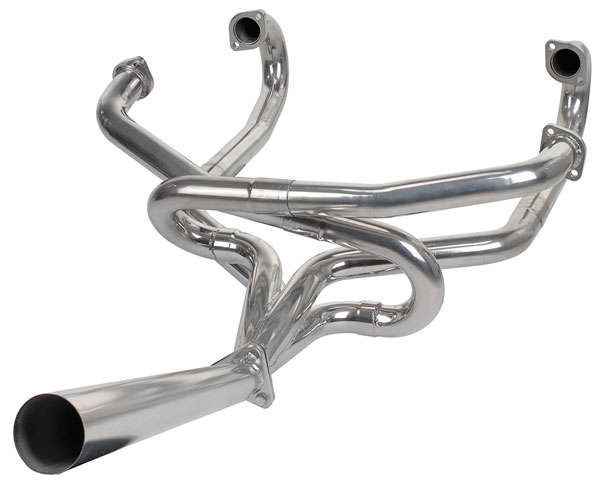
Friday, I went to The Bug Stop and picked up a couple of things, most importantly an exhaust system. It’s an EMPI 3647, which is basically a 4 into 1 with a single muffler that exits to one side. There is a very slight “concern” that the included muffler may be too quiet, but that’s a pretty minor concern. ![]()
The weekend was far too busy to allow any trike time, but this week may offer some opportunities.