I have left the gate camera battery alone, other than monitoring it, for 10 days. Love the Shelly. More on that someday. Anyway, 11 days, technically. Today isn’t over, but 10 nights for sure.
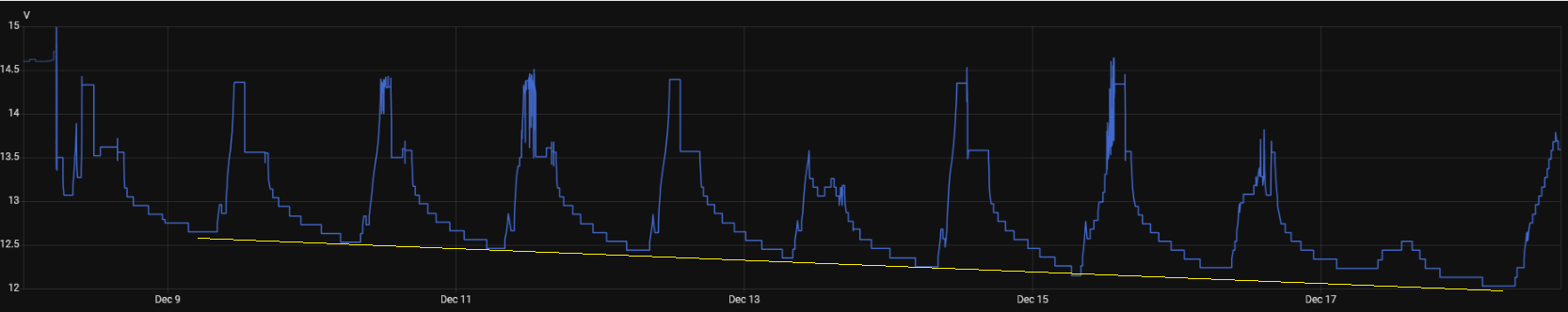
You may need to click on that image to see the detail, but there is a pretty much linear decline in the “peak” nightly discharge. Overnight December 9-10, it discharged to 12.65 volts before a sunny day recharged it to 13.5 volts. Every night, it would discharge a little lower, then a sunny day would bring it back to 13.5 volts. December 13 was cloudy for much of the day, so we didn’t get a 13.5 volt peak, but the 14th and 15th were sunny enough. The 17th was dreary and today, the 18th has been sunny thus far.
However, each night, the battery discharges a little lower. 12.65 volts the first night, then 12.53, then 12.46. Each night lower until last night, 12.03 volts.
Here’s the rub. I don’t know if this is just a normal decline after the sorta mega charge from the AC powered smart charger and it’s just slowly settling back after that, or if it’s a symptom of a problem and I just happen to have a big enough battery to help make it take a long time to show up.
I do have an apples to pears example to compare with. I put the Triplett logger on the gate opener battery for week or so.
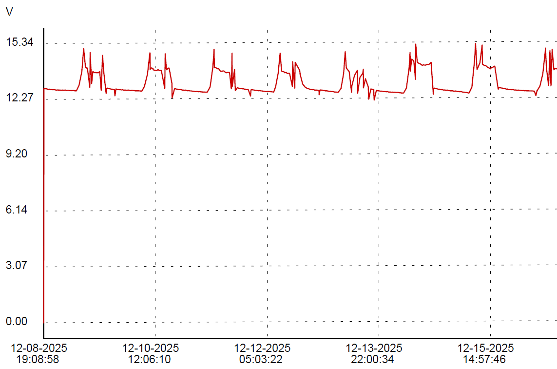
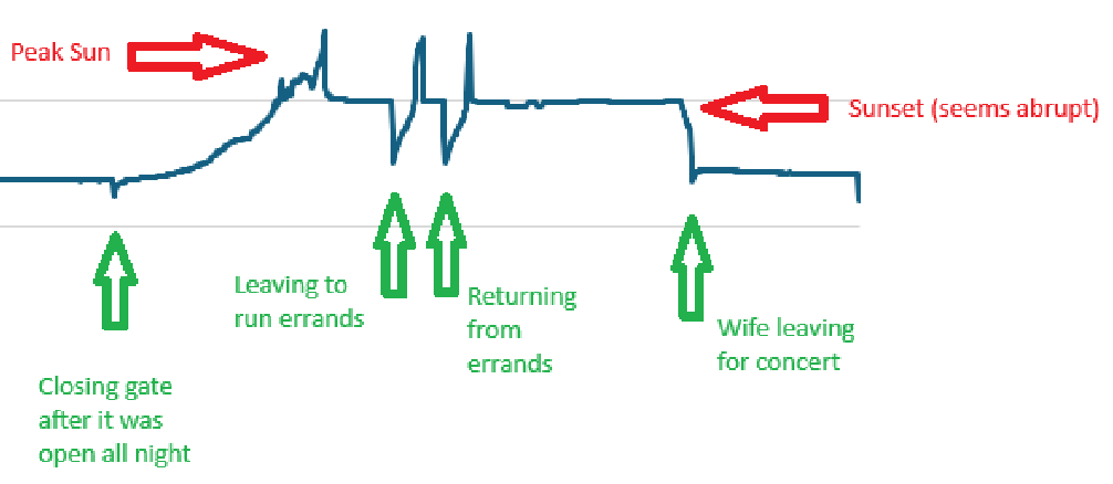
First, I love the sharp little peaks that (probably) show gate usage. If I get ambitious before this gets posted, you’ll never see this sentence, and will instead see my evidence that the little jabs in the opener chart correspond with gate operations. Or maybe because I just like this paragraph I’ll leave it anyway. You’re not the boss of me!
See, I told ya.
Dec 16 gate activity:
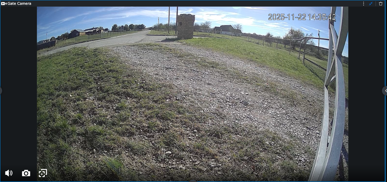
I am not sure what causes the positive spikes. There is nothing obvious in the gate camera at those times.
The two battery deployments are exactly the same thing except that the gate opener has an unknown but likely minimal charge control built in instead of a purpose designed solar charger controller, it has a small lawn tractor battery instead of a large deep cycle battery, it’s only a 10 watt solar panel instead of a 100 watt panel and the load is almost nothing most of the time instead of a camera, a WiFi AP and a Shelly UNI running 24/7. Both batteries are black plastic, made by the lowest bidder, so there’s that…
Since the data from both logging sources are available in CSV format, I thought I would try to match up the charts in a spreadsheet, but there are significant enough differences between the data sets, due mostly to the delta method employed by the Shelly UNI, that it is not trivial to match them up. The Triplett has even time between samples, the Shelly samples only when a significant enough change occurs. I am certain I *can* match up the data, but I’m not sure it’s worth the effort.
Even so, one can kinda look at the data and, even if I can’t easily share a spiffy visualization, I can report that the opener battery bottoms out at 12.67 volts consistently, give or take a couple of 100ths, each night in the logged data, unlike the big battery with the big panel, that seems to progressively lose ground every night.
Then again, maybe 10 nights isn’t enough to know the bottom of the pattern yet.
And who knows what spring and summer, with the sun higher in the sky will bring.
My last post was last Friday. This is Monday. The gate battery had an exciting weekend.
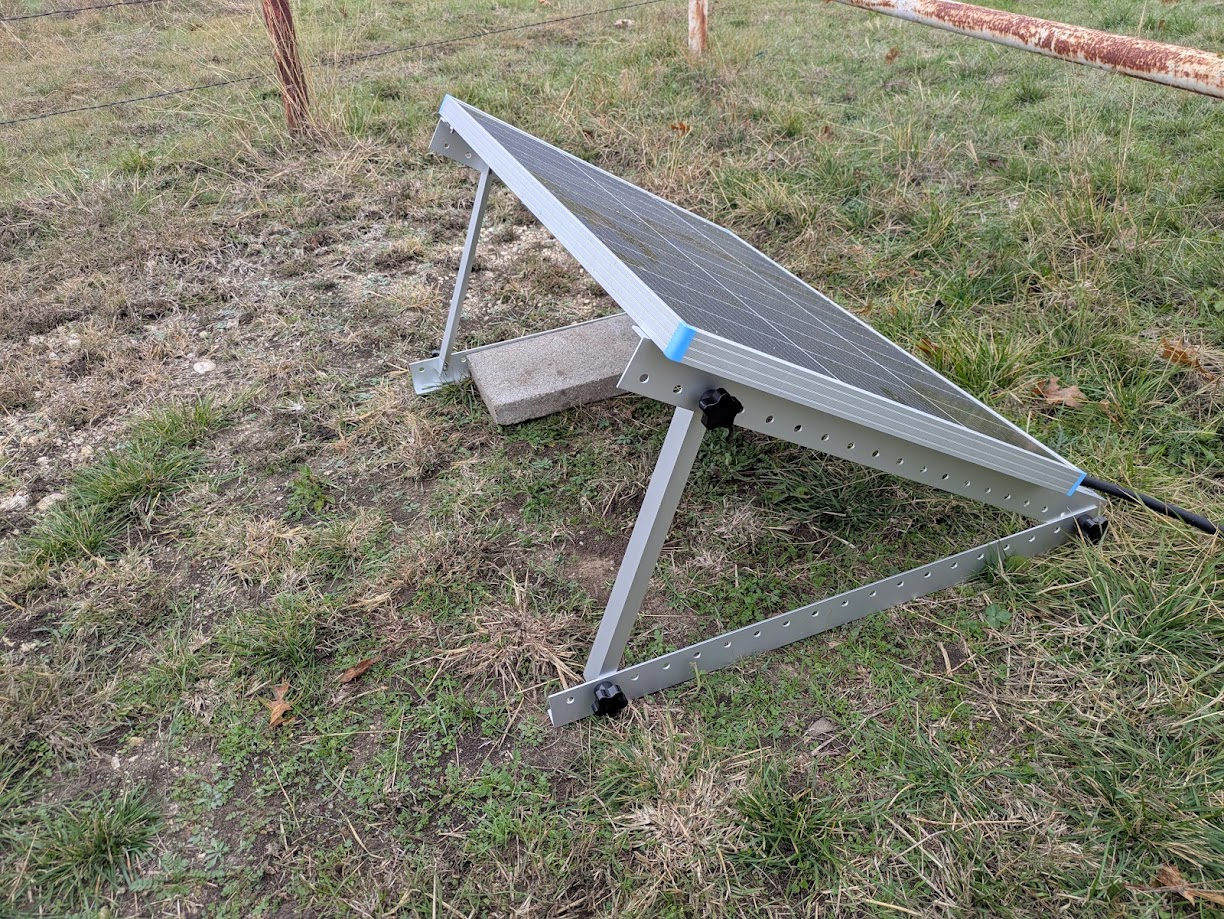
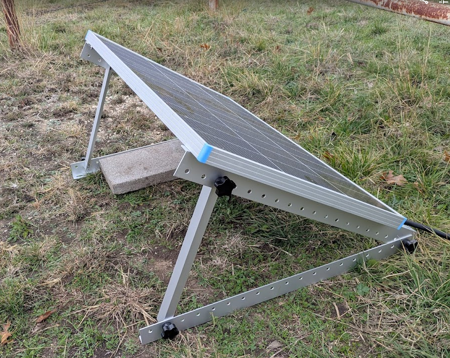
Late Saturday morning, I finally got the official Renogy Solar Panel Mount Brackets deployed.
It is adjusted approximately to the theoretically ideal angle, which somewhat understandably matches the latitude of the location, in this case 33-ish degrees. That doesn’t account for the few degrees off level where it is thrown on the ground, but its more of a rule of thumb anyway. Longer term, I think I will attach it more firmly to the ground than with the gravity afforded single cinder block cap. Also, the cabling is still far from safe from any mowing implements.
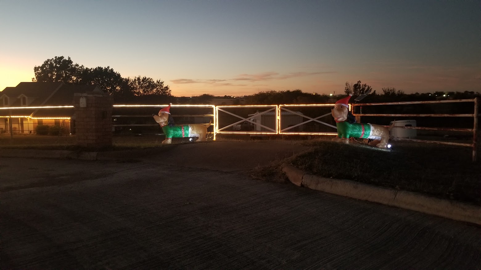
For the rest of Saturday, we did unrelated stuff. Sunday, however, I set up our usual fence Christmas decorations, which is modest, but enjoyable. Lighting on the fence and gates, plus a couple of inflatable elfy dachshunds.
One nice side effect of these decorations is that I run a extension cord from the house all the way out to the gate, so for a couple of months, I have mains power available at the gate. So, once I had the basic power distribution in place, put my smart charger on the gate battery and left it.
I deploy a Home Assistant controllable switched outlet for these decorations, along with automations to turn them on a sunset and off at 2:00AM. Since I wanted to leave the charger running, I disabled the automation to turn off the decorations.
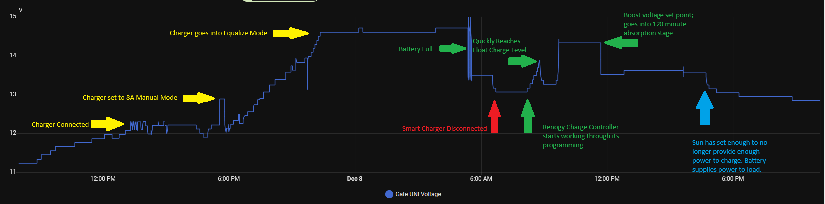
Leaving the charger on overnight definitely had the desired effect.
There is a lot going on here. Click on the image below for details.
Of a mildly entertaining nature, the outlet switch I run these lights on reports power use. Right now, with just the lights and the dachshunds, it is drawing a little less that 200 watts. Interestingly, it varies quite a bit, between 170 to 192 watts. I suspect some variation from wind affecting the inflatables, but I would have to care enough to investigate to know for sure. However, while the smart charger was connected, it ramped up to 420 watts peak around 10PM, then back down to baseline 180ish by 5AM or so, including a decided bump down at 5:20AM that corresponds with a bump down in Gate Battery voltage, which I presume to be the Battery Full mark notated above.
Of a even more mildly entertaining nature, when I installed the Shelly UNI on Friday morning, I apparently knocked one of the Triplett clips off the battery terminals and didn’t notice it until Saturday when I was attaching the mounts to the solar panel. The two logs are otherwise very close, within their respective limitations.
Since I now have essentially live logging on the gate battery, I redeployed the Triplett onto the gate opener battery, which is a separate thing. The Mighty Mule gate controller has its own small solar panel, probably 12-15 watts, to maintain it’s rather modest requirements. The opener draws nearly nothing until called upon to open and close the gate, which doesn’t happen very many times per day, often not at all some days. Upon connecting it, it was reading 12.89 volts, so it’s probably pretty healthy. I will try to leave that logger on there for several days to see what that battery does.
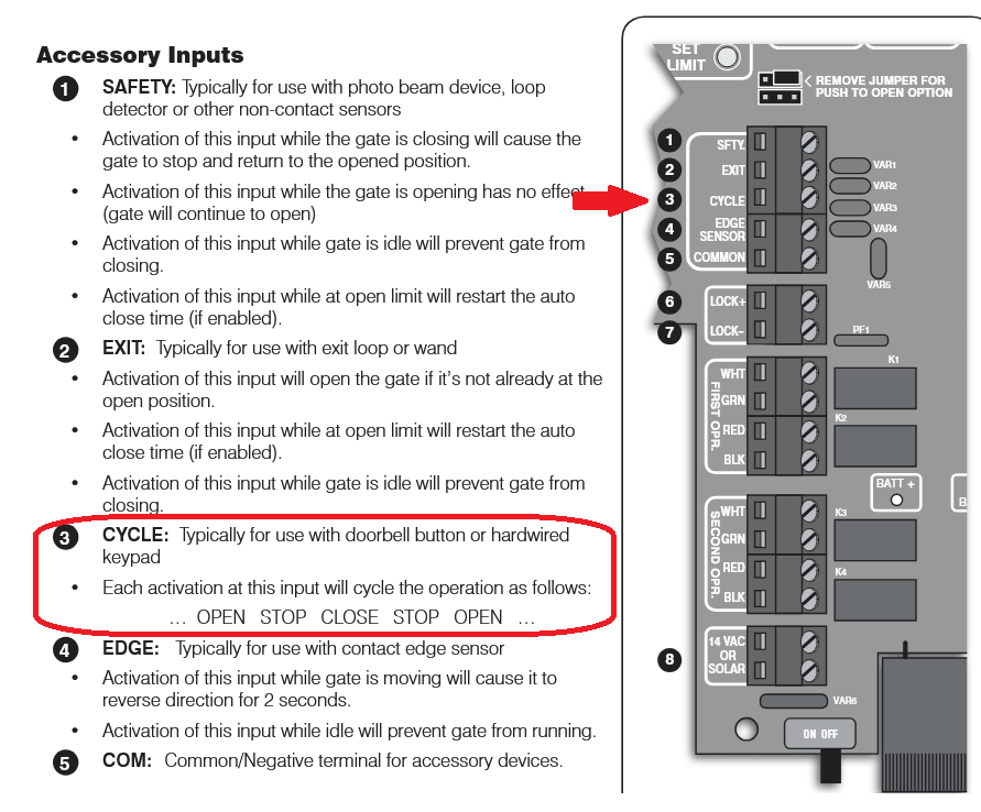
Speaking of gate opener, this is what I will probably connect one of my Shelly UNI outputs to, to be able to open the gate from Home Assistant.
I need to nail down the behavior of these outputs. It sounds like I can have it momentarily close with a button push, but the verbiage is not stupid clear 🙂
Ok, I still have my legs, but I am kind of obsessed with this battery thing.
It has been about a week since my last confes… post.
Some of this post will go back and forth, time-wise. I am more interested in covering each subject rather than rigorously maintaining a timeline.
The plan was to leave the new 100 watt solar panel in place as long as possible to see if it can catch up charging the new battery. Unfortunately, the weather saw through my ruse and has conspired to be cloudy and sometimes rainy, limiting the solar flux.
By Tuesday, I decided to help the battery along by connecting a mains powered battery charger, using a 800-ish watt-hour power bank. I knew it would not last all day, but I also knew it would be a powerful boost for the battery.
Wednesday morning, I pulled the voltage logger history, then put it right back on to continue logging.
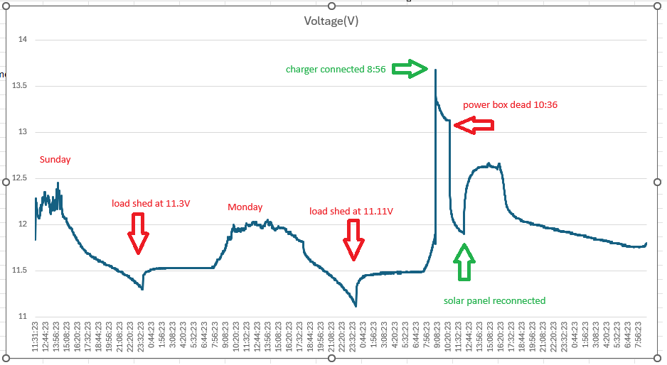
There were a few key moments in the data:
When the battery voltage dropped to 11.3 volts by about 11:45PM, the charge controller shed the load, resulting in a small voltage boost. Interestingly, it did not restore the load until 5:45PM Monday, well after the peak battery voltage well over 12 volts.
By 11:45PM Monday night, it had again shed load, but it seems important that it shed load at 11.11 volts. This is, to a lead acid battery, significantly lower voltage than the 11.3 volts where load was shed the night before. Very curious.
Around 8:00AM, we actually had a sunny day the solar panel began adding a sharp rise to the battery voltage.
At 8:56, I connected the external charger. The screen display on the power box estimated 3 hours of runtime, but it was wrong. The box was depleted at just over an hour and a half. Since I had set an alarm to check on it in three hours, it was well shut down by the time I checked it. I pulled the charger off and put the power box in the garage to recharge it, but I left the logger in place until Wednesday morning.
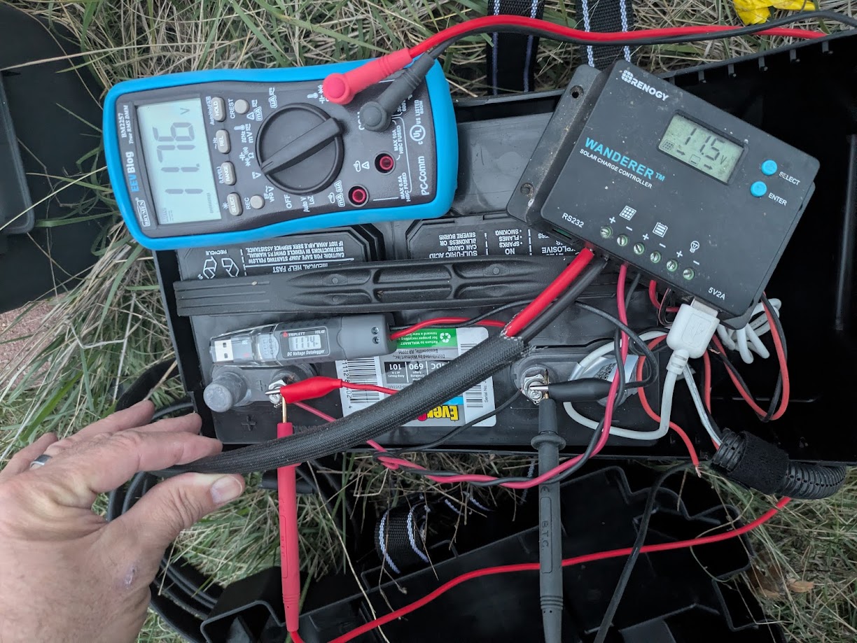
When I reconnected the panel on Tuesday, I was smart enough to take my 2nd string cheapy meter up there to see what the open circuit voltage was on the solar panel, which was 23.9 volts. Ironically, I kind of noticed at that time that the charge controller and the voltage logger were slightly different and I remembered the voltage logger as being about 1 volt lower than the charge controller. However, with a meter in my hand, I did not think to check it and compare at that time. Typical.
Early Thursday evening, I took my good meter out there and compared the three readings. They were all close enough to not really matter, though the charge controller reads the lowest by 0.2 volts, possibly a significant number when dealing with lead acid chemistry.
The coolest development is something I have wanted for a long time, a way to monitor the voltage remotely. I had mentioned using an ESP-Home device, which would be inexpensive and pretty easy to build, plus I have already made a few similar devices and likely have everything I might need on hand.
Then again, I discovered that Shelly makes an affordable device that does what I need right out of the box.
For my purposes, it is a WiFi device that talks to Home Assistant using MQTT, runs on 9-28 volts DC and can measure 1-30 volts DC.
It also has two digital inputs, a pulse counter input, two digital outputs that can drive 300ma, and it can operate a variety of one-wire devices, such as temperature and humidity sensors. I see a Home Assistant gate opener in my future. I only wish one unit could monitor two voltages so that I could almost monitor the gate opener battery without deploying a second unit.
It was almost trivial to get it working. This is not really a tutorial, but… I put the Shelly app on my phone and give it Bluetooth permissions. I powered the UNI with a 12V battery pack that I use for various things. The app found the UNI device immediately. I configured it to join my IoT WLAN, then browsed to it to set it up.
First, I set up MQTT. All I had to provide was the IP and MQTT port of my Home Assistant and it pretty much immediately showed up in devices.
I noticed that there was no voltage sensor showing. To enable that, I had to go to Peripherals in the UNI setup menu, click the + button to add a peripheral and add Voltmeter. There are several useful settings, such as a friendly name, measurement range and some custom math and units that can be applied to the measurement before it is reported. For example, you might measure 4 volts, but 4 volts from a strain gauge might mean 9 pounds of grain left in a hopper, so you can do some math and report 9 pounds instead of 4 volts. You can also set up automations from within the UNI device itself
“Delta Threshold” is worth spending a little time on. The Triplett logger takes a voltage reading once every configurable time period. The longer the duration between samples, the longer you can collect data before the memory fills up. The Shelly UNI instead watches the voltage and only reports when the voltage changes a certain amount. The minimum and default is 0.1 volts. This makes for a much more efficient use of database space, but a blockier uglier graph.
Everything else was just minor tweaking of Home Assistant stuff.
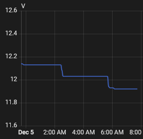
I left it connected to the battery pack overnight.
It was several hours between 0.1V drops, from 12.14, to 12.03, to 11.92 volts.
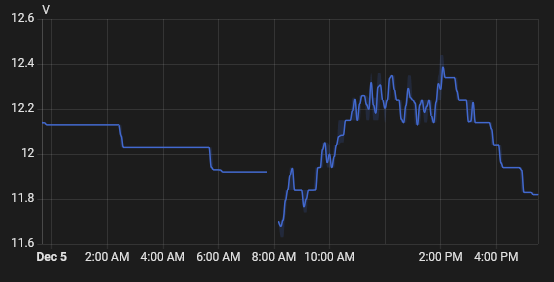
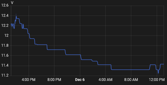
This morning, I added a little more wiring and connected it to the gate battery. We’ve had a reasonably sunny day.
It’s only one day, and the first semi-sunny day in several, but I am disappointed in how rapidly the battery voltage is dropping. Of course, it didn’t peak very high, so that could be a factor as well.
I am thinking of running a cord out there and running the charger for 3-4 days to put a real solid charge on this battery so that the solar can really do just maintenance charging.
It is now Saturday morning and rather than add a whole post just for this, I though I would append to this one.
I took the 30 minutes or so that it took to build and attach the mounting brackets to the panel.
This is set to the reasonably ideal angle for a panel that is the same as the location’s latitude, 33ish degrees in this case, measured imprecisely with a speed square during assembly and using the holes that came closest to that imprecise measurement.
It is a cloudy day and it was a foggy morning, so I can’t expect a lot of energy today. I did find the little dip from the removal of the panel during construction of the brackets a little chuckleworthy.
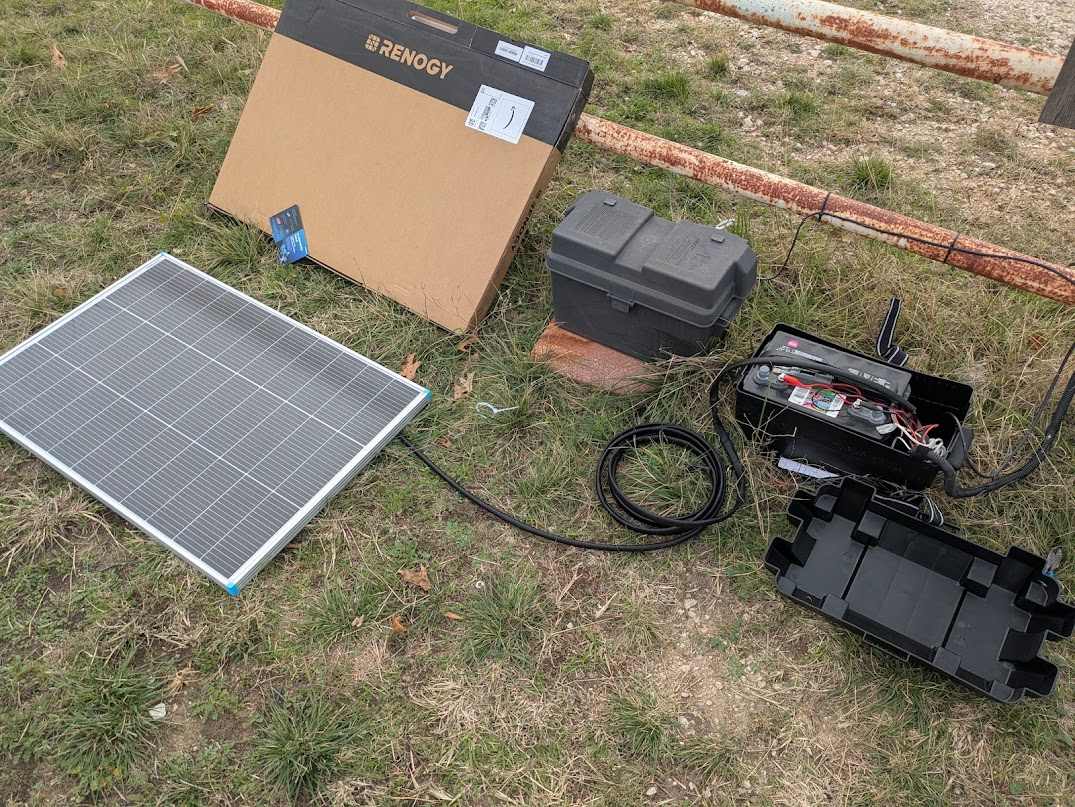
I decided on a 100 watt Renogy panel, along with an appropriate cable to connect it with. It has been here for several days because I realized that it is far too large to mount where the little 25 watt panel is without major redesign of that mount.
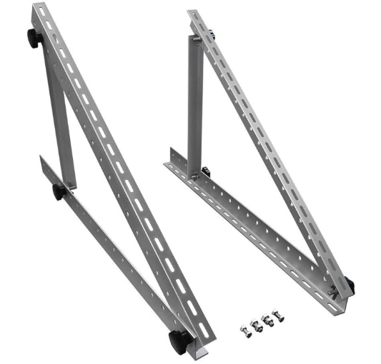
I decided to order a simple set of angle mount brackets for it and to mount it to the ground, probably on something else attached to the ground, a couple of treated lumber 2x4s or something. It will be a few more days before they arrive.
Meanwhile, I noticed when looking at one of the other cameras that the gate camera was down. That lead me to check the Gate AP and sure enough, it was down as well.
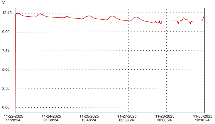
I retrieved the voltage logger. With several days of logs, I can confirm my suspicions that the 25 watt panel cant provide enough power to run the camera and AP during the day with enough left over to gainfully charge the battery. The battery voltage trends downward over six days until the charge controller sheds load. The deep cycle marine battery just extended the time that the system could tolerate the undercharge conditions.
It appears that everything connected to the charge controller remained powered up until the ugly bit of charting near the end. The small charging peak on 11/24 corresponds to a rainy cloudy day with a little bit of sun in the afternoon. The really flat part near the end shows both a couple more cloudy rainy days and the weirdness that a fairly deeply discharged battery can display.
Once I saw this chart, I thought it might be better to connect the new panel, even without the proper brackets. Perhaps laying on the ground, it can charge the battery better than the small panel.
Today is a cold and mostly cloudy Sunday. It took less than 30 minutes to unbox the panel, cut the connectors off one end of the cable and connect it up to the charge controller. The controller was “stuck” in the E01 state, so I disconnected the battery and the solar panel to clear the error. When I reconnected everything, the solar panel was showing 12.9 volts at 1.4 amps, which is about 18 watts. It was enough to power up the AP and camera. Even laying flat on the ground in cloudy weather, this panel is providing almost as much as the old panel is even capable of.
A little later, I saw that the sun was valiantly trying to come out. At that point, the charge controller reported that the panel was puting out 12.4 volts at 2.6 amps, which is 32.24 watts. While I was looking at it, I manually tilted the panel towards the sun and got it up the 3.3 amps for a peak of 40.92 watts.
I am cautiously optimistic.
I do need to solve some installation issues. The cable from the panel needs to be protected from the elements and the weed eater and right now, it’s just coiled up on the ground. Once mounted, the panel being low to the ground may be subject to mud splatter in heavy rain, so keeping it clean may become a thing.
Interestingly, there is no reason I can’t connect these two panels in parallel. Solar panels will operate at essentially whatever the lowest voltage panel is and the resulting amperages will sum. In practice, it is unlikely that I would ever get an actual 125 totals watts from these two panels, but they will add together. There may be some lost efficiency; we will just have to see what gives. The wiring from the 25 watt panel is currently just sitting there unconnected inside the battery box anyway.
In my last post, I posited that my gate camera connectivity issues might not be connectivity issues at all, but rather power issues, complicated by the camera’s irritating tendancy to lose its WiFi configuration when it loses power.
Eschewing proper scientific method in favor of a rapid solution, I approached this from several directions simultaneously. I installed a (probably unnecessary) mesh WiFi AP at the gate to ensure good WiFi signal out there. I replaced the probably near end-of-life lawn mower battery with a new marine deep cycle battery. I put a voltage data logger on the battery to see if the solar panel and charge controller I have is capable of charging it. I submitted a ticket to Amcrest to find out if the loss of configuration is a feature or a bug.
I kind of hinted that I was having trouble getting the camera to connect to the network at all anymore. I was blaming this on the tendancy of some network devices to latch on to a particular AP, even if there is a logically better AP to connect to. I presumed that the camera was desperately trying to connect to one of the APs in the house and the now stronger new Gate AP signal was probably interfering. Unfortunately, it still did not connect when I powered off the Gate AP. Power cycling made no difference.
Meanwhile, Amcrest suggested that the loss of the configuration is not normal and that there is a “newer” version of firmware available for the camera. I treked out to the gate this morning to attempt again to connect and upgrade the firmware. Not only would it still not connect, but I noticed that the app indicates that the last version of firmware it knew about was newer than the one the Amcrest tech suggested.
I decided to take the camera inside to attempt connection from inside the house, first via PoE. Turns out, this camera does not appear to run on PoE, at least not PoE as supplied by my Ubiquiti switch. The other Amcrest cameras I have do run on this switch, so I’m reasonably confident that it just doesn’t do PoE afterall. So, I provided appropriate power and found, almost unsurprisingly, that it still would not connect to WiFi, although all the steps up to the last did work. Factory reset made no difference.
What finally got it connected was DC power and wired ethernet. The camera works fine, just apparently no longer on WiFi. And the firmware is indeed the latest offered for that model, newer than the Amcrest tech suggested. Shrug. There are some places where I can redeploy it.
My best option now was to reinstall the ADC2W that was removed when the previous Renogy USB output failed. I changed cameras primarily because the ADC2W WiFi signal was weak. With the Gate AP in place, that should not be a problem now.
The only thing left is the battery log.
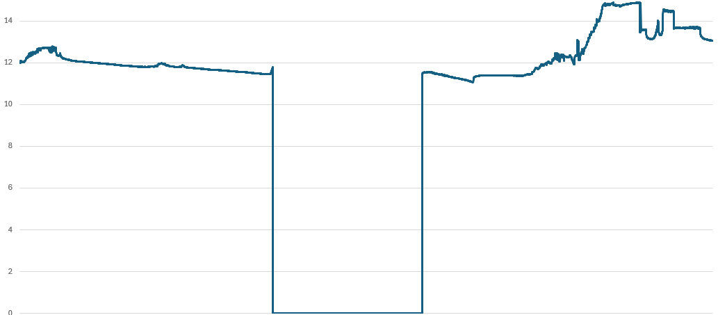
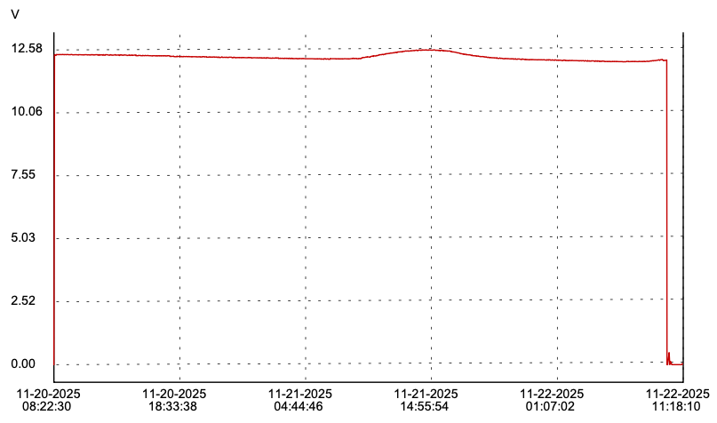
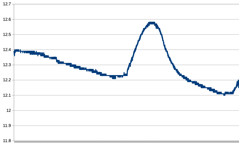
The chart provided by the logger’s own software is scaled to include the zero volts from the first few samples before and after I connected it to the battery. By making my own chart with the CSV data, I can scale it to exaggerate the two points that was was able to glean from this slightly more than 48 hours worth of data.
The first day, November 20, was a rainy and cloudy day. There was not enough sunlight available to offset the power draw, not at all.
Beginning about 09:00 on the 21st, there was enough sun to effectively charge the battery, until about 16:30, when the battery voltage tapered off fairly rapidly. Sunset was officially 17:25. By 20:30, the battery was back down to where it had started at 09:00 and it would continue to drop even lower until about 06:00 on Nov 22nd.
This is only 48 hours of trend, but it seems likely that my 25 watt panel is not enough to recharge the battery with it’s nominally 10 watt or so load. I need to get a bigger panel.
Do I double the power to a 50W panel, which is a more manageable size? Straight to the larger 100W panel that might be overkill, but is only 30% more money?
Some time ago, I discussed a connectivity issue with the gate camera, specifically adding an outdoor wireless AP to strengthen the signal to and from the camera. Since that post (but undocumented, mostly because I am lazy), I upgraded the antenna on that AP to the higher gain somewhat directional patch antenna.
The camera continues to disconnect randomly.
These days, however, it does not reconnect without human intervention and not before I dropped more networking dollars on attempting to address this would I realize that it is probably not actually a networking issue. More on that later, especially since I made it worse.
After just accepting that I was going to have to reconfigure the camera occasionally and tolerate it not working between the time that it goes down and the time I get around to reconfiguring it, I finally decided to drop a few bucks on the networking “solution”.
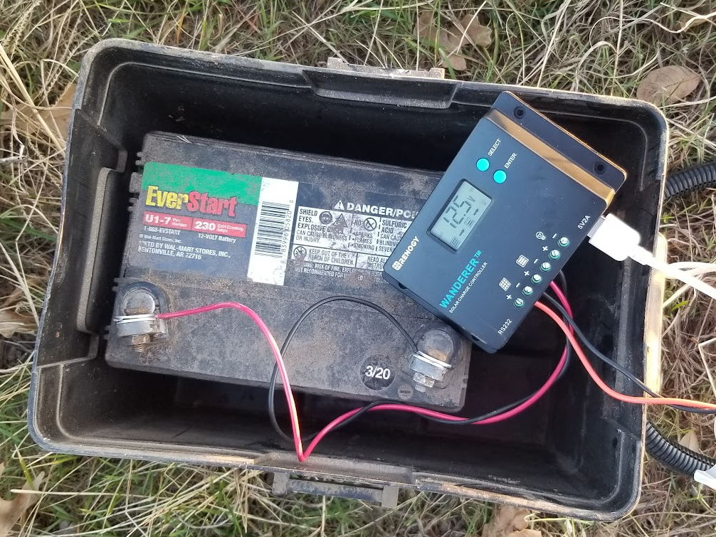
First, a bit about the power system.
The gate camera is powered by a lawn tractor type of battery, though not directly. It is connected to a Renogy Wanderer solar charge controller. This is a nice little 10 ampere PWM charge controller with a surprisingly long list of features for about $50. The whole thing is charged by a 25 watt solar panel pointing largely south.
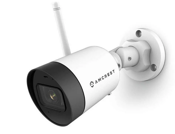
The original gate camera was powered by a USB cord and this charge controller was originally chosen because it has a pair of USB A power outlets. I don’t know exactly what happened to it, but that power outlet died after a year or two (I suspect water intrusion) and when I replaced the charge controller, I also replaced that camera because it did not have an external antenna and I hoped that a better antenna would help the connectivity issues. The new camera can be powered either directly on 12VDC or via PoE. No PoE at the gate, so 12VDC it is.
That current gate camera is an Amcrest ASH42-W.
The Renogy Wanderer shows the occasional error code, if one bothers to look at it. I have accidentally shorted the output, resulting in a code E04. Disconnecting the battery and solar panel will reset. Code E01 means that the battery voltage ran low. Apparently there is a feature where the Wandered will shed the load to protect the battery from deep discharge. It is unclear if that is concurrent with the E01 error message, but I suspect it is. There have been times when we have had several days of stormy or cloudy weather and the battery would understandably not be kept charged. The solar panel was not as securely mounted as is needed to be and wind turned it away from the sun once. On rare occasions, we have had snow or ice obscure the panel. Any of these situations will throw an E01 on the display, but when the charger brings the battery voltage back up to a safe threshold, the power output is apparently turned back on automatically. I don’t think the E01 is cleared without some kind of manual intervention. The documentation seems to indicate that a power off restart is required, but I’ve never needed to do that. The E01 just goes away when I mess with the buttons.
One thing that this camera does (badly, in my estimation) is lose it’s WiFi configuration when it loses power. [edit: just today, I have submitted a ticket with Amcrest asking if this is normal for this model camera; I have other WiFi Amcrest cameras that don’t do that] You have to use the Amcrest app on a phone to connect to the camera, authenticate to the camera (which *does* manage to save the admin password, just not the WiFi info. Argh!) and reconnect to the WLAN. One ….. lets call it a characteristic…. of the app is that it shows the available SSIDs and a little symbol indicating the signal strength, but it shows me multiple listings of the same SSID, usually with differing signal strengths. I am guessing that this is somehow picking up the same SSID from different APs. This seems to severely complicate choosing an SSID to connect to.
Still of the (probably misguided) opinion that my camera disconnection problem is caused by poor network connectivity, I finally spring for a mesh capable AP to mount by the gate so that two APs can talk to each other, but the camera will only need to reach the few feet to the nearby AP. Oh, how naive that idea turns out to be.
The Ubiquiti AC Mesh AP is interesting in that it’s only power option is 24V PoE. I had to do a little digging to find something suitable to power it. Specifically, what it needs is a 24V passive PoE injector that is powered by 12 to 48 volts DC. There are gobs of AC powered units, but not many DC powered. In any case, I found one for $20 from Amazon. As for the AP, I generally prefer to order Ubiquiti items directly from Ubiquiti, but the $99 price was the same and Amazon had it, so I got both items next day.
Then I waited two or three days to install them.
The installation of the AC Mesh went as Unifi stuff usually does, pretty pretty much without drama. I plugged it in to my switch in the house first to adopt it and configure it as a mesh child and the garage AP as the mesh parent. Then did a kinda quick and dirty installation at the gate, where it came right up and connected. My phone was able to connect to it immediately. Internet speed test was exactly as good as from inside the house. The mesh speed limit is something like 867 Mbps and my Verizon 5G is only good for about 250 Mbps at best, so plenty of headroom.
Now is when I began facing my first problems with this new setup.
The camera would not connect to the network at all. It would connect to my phone for configuration, but then would just continue to blink not connecting to any actual WLAN. This is also where the confusion borne of the multiple duplicate SSIDs makes things even worse.
If I turned the transmit power of the AP down to low, the camera might connect to the WLAN, but it would not connect to that AP. It connected to the garage AP, the one it usually connects to when there isn’t one 2 feet away. In related news, detailed below, my other WiFi cameras stubbornly don’t connect to the AP that makes the most sense for them either.
If I power down the Gate AP, connect the camera to WLAN, then power up the Gate AP, the camera still doesn’t roam to the Gate AP. By itself, this isn’t surprising because roaming is a fairly sophisticated behavior that a relatively simple network device may not exhibit.
Here is the biggie and the thing that finally put me on what is probably the actual issue here. I got the camera connected and the Gate AP on low power and left it overnight, hoping that maybe the camera would reconnect later and choose the better signal. Instead, I found the camera disconnected in the morning and when I started looking, I found the Gate AP to be offline. Hmmm
Hmmmm, indeed. When I went to feed the horses, I went by the gate and looked to verify what I now suspected. Sure enough, the camera and AP were both without power and the Renogy was displaying E01 and it finally got through to my thick head that, probably for this entire time, I have been running the battery down to load shed, the Renogy restores power when the battery is back to a reasonable level and a few days later, when I get around to resetting the camera, always after work when the battery has had all day to be charged back up, I haven’t been suspecting power, but network. So, lets “solve” the problem by adding more power draw to that marginal battery.
Armed with this new-to-me knowledge, I am taking a different approach. I still kinda want to solve the network problem wherein the camera will connect to the Gate AP and enjoy the better bandwidth that should provide, but I need to solve the power problem for sure.
I ordered a budget data logger with the intent to log the voltage on the old battery, specifically to see absolutely if it was actually running down overnight. I also got impatient waiting for the data logger to arrive and also bought a new battery, a deep cycle marine battery, which is arguably a much better match to the purpose than the lawn tractor battery.
Sidebar, kinda: The gate opener has run on a lawn tractor battery for years. The gate opener has been in service since about 2012 or so, , though the design lifetime of that class of battery has been a factor in having to replace it a couple of times during those years. However, the load from the gate opener on it’s battery is quite different. It spends the vast majority of it’s time drawing a few 10’s of milliamperes, then occasionally, a couple of amps for a minute to open and close the gate on demand. This tiny demand is completely within the charging power delivery of the 8 watt solar panel that was available from the gate opener manufacturer. The camera, on the other hand is a continuous 24 hour, 7 day load specified by the manufacturer only as “< 4.8W”, which should be read as “up to 4.8 watts”. In dark conditions, the camera turns on built in infrared illumination, so it makes sense that at night, when there is no solar charging happening, the camera is potentially drawing the most power that it can, probably about 4.8W. In new condition, the lawn tractor battery I had in place *should* be good for about 420 watt-hours, so with just the camera and allowing for some draw/loss in the charge controller, rounded to 5 watts, a freshly charged battery discharged to 50% should be good for 42 or so hours, but I’m getting more like 8 or less. It is apparently not running at full capacity and/or not getting fully recharged. The battery is no longer 420 watt hours and / or the 25 watt panel can’t replenish the watt hours used overnight and eventually battery runs dead enough that the charge controller has to shed the load. The battery gets a chance to catch up enough for the load shed to clear, but a day or two more of use, runs it dead again. Then I added up to 8 more watts of power draw for a wireless access point.
I really should put the old battery back in and log the battery for a week or two to verify this theory, which is a thought that is out of sequence here and will make more sense after the next couple of paragraphs. Sorry. Editor’s prerogative.
I installed the new battery last night. With the Gate AP operational, I could not get the camera to connect and I got fed up with trying, so I left them as is overnight.
The datalogger was delivered late last night, about 9PM (Amazon… amiright?). I was already comfy and didn’t bother fetching the box. So, of course, it started raining in the predawn hours. The box was soaked to disintegration by morning, but the logger was fine.
It’s a Triplett VDL48. Cute little thing. Kinda weird in a couple of ways. The manual is close to useless. It took some research to determine that you must use their proprietary app to set the logging parameters, apparently each time it’s used. It does nothing particularly useful right out of the box. However, once I knew that I needed the software to make it go, it was a pretty simple matter to set it up. I set it to log in 10 second increments, started it logging then braved the rain to attach it to the battery.
UGH! I bought a new battery box for the new battery, one with room for the battery and both the Renogy and the PoE injector. Battery boxes are designed to vent hydrogen and batteries themselves are largely waterproof. So the tiny vents molded into the lid of the battery box are normally not a problem, but I have electronic equipment inside my battery box and I discovered that it was getting wet in the rain from these vents. I had discovered this previously in the other battery box and had addressed them with a piece of plastic and epoxy. Today, and needed something more expedient, so I grabbed a slightly nasty towel and a roll of electrical tape from the garage and returned to the gate. I dried off the vent area and used two hastily ripped strips of tape to cover each vent area, as well as at least partly patting the Renogy dry. It was directly under one of the vents. I do have a spare, just in case.
So, as of about 4:30 or so this afternoon, the battery voltage is logging to the Triplett toy. It was 12.37 volts when connected. Also, with the rainy weather, the Renogy reported the PV voltage (photovoltaic; the solar panel input) at 10.something, so less than required to actively charge the battery. It would be awesome to have a two channel logger. I don’t care enough to buy two at this point. It’s 9:50 PM as I edit this paragraph and the Gate AP is still up, so the battery has not run down to load shed in the rainy dark.
Earlier, I mentioned an irritation that I also need to address. This is a problem that has come up with several devices in my network. In short, there are a number of WiFi devices that insist on connecting to APs that are not only not nearby but are often the least nearby AP that they could possibly select.
I have a AcuRite weather station. The sensor unit outside communicates with the indoor unit via 420-something MHz RF, but the indoor unit does WiFi and via WiFi, can connect to the Weather Underground network to post my collected weather details online. This WiFi happens to be using an Espressif ESP32 MCU, which for reasons I can only guess at, won’t connect to AP in the ceiling of the room it is *in*, a mere 10-12 feet away, but rather it will connect only to the AP in a hallway on the other side of the house, where it enjoys one of the weakest received signals in the house.
Similarly, I have another WiFi camera, a different model than than the Gate Camera, but the same Amcrest brand. It is deployed in our barn, set to monitor the water trough for the horses. It is about 30 feet from the AP that is in my workshop in the barn. Instead, it will only connect to an AP in the house, about 80 feet away and through a number of walls.
I have two EPS8266 based homebrew temperature sensors in the garage. One has a probe stuck through the wall to the outside. The other has an internal temperature sensor, but also a counter input that reads a water flow meter. Both of these are 10-20 feet from the Garage AP. On connects only the the Hallway AP in the house, which is at least arguably equal linear distance, though with several extra walls and lots of furniture for interference. The other is literally 10 feet beneath the Garage AP, but connects instead to the Kitchen AP.
All of these exasperating devices at least have one thing in common in that they are less sophisticated network devices, at least as compared to smart phones, laptop computers, etc. They may be making their choice based on the lowest numeric MAC address or some other equally arbitrary but mathematically simple calculation.
Thus far, no amount of Googling has revealed a solution to this particular problem.
I’m sure my eclipse day story is not much different than untold thousands of others, but I only have mine to tell. 🙂
My long long time friend KD and I started loosely planning for an eclipse capture trip quite early, as one should. Actually, we started planning for the October 2023 annular eclipse. We both live in Texas, but a good four hours apart and neither of our homes were directly on the October 2023 path. Soon, however, I realized that I already had conflicting plans for that week, so I missed that one. That made April 2024 that much more important. I had vacation time to burn, so planned for Monday and Tuesday of that week so that I could do whatever travel I wanted to do.
As we got closer to the date, we tried to find a place that was a similar daytrip drive for both of us and it was looking likely for a lonely stretch of highway near Llano. Conditions changed, as they often do, and KD was going to be able to make it more than a day trip, so I started looking for places closer to me, intending to host him here. As it turns out, the path passed through a town near Sulphur Springs where I know someone who owns a bit of land. I contacted her and a couple of astrophotography nerds were just the thing she needed to complete her eclipse day plans. She asked for our T-shirt sizes, so I knew something was up. 🙂
The other part of planning that I was partly successful with was the two part task of getting things together for the shoot and practicing with them. I was better at gathering than having 😉 Of course, the gathering was done in time for the October eclipse.
The general plan for the day was to use my Redcat 51 telescope and venerable Canon Rebel T6 with a solar filter and an intervalometer to take about one picture per minute and use my tracker to make it easier. Happily, for that part of the plan, all I needed to purchase was a solar filter to fit the Redcat.
I also wanted to have an second camera for manual use. I found that I could get decent price on used Canon cameras on Adorama. They had a Rebel T5 for less than $100. The T6 has WiFi and NFC and a higher resolution screen, but otherwise the T5 is essentially identical to the T6, making them largely interchangeable for most of my uses.
Editors note… for reasons I can’t explain, I am picking up the editing of this post almost a full year after the event and everything above this paragraph was written a year ago. It just shows that if I don’t jump right on a blog post, it suffers.
Now it just came down to making sure that KD and I coordinated our travel plans and that we gathered pretty much everything vaguely photographically related that either of us own. He came to our house a day early and the morning of, we headed to North East Texas. After all the introductions were made, it came to light that the proprietor had indeed made a small event out of it and had lunch and T-shirts for a dozen or so guests.
We set up all of our gear. With all the boxes and bags we brough in, it looked like we were there for a movie shoot. Sadly, I did not get any good detail shots of the gear once it was set up, just this wide shot of the site.
In the foreground is KD’s setup, a Canon DSLR and filtered lens on a tracking mount, secured on a weighted tripod. Behind is my setup, similar in that it is a Canon DSLR and the Redcat51 with a filter on a tracking mount secured on a big tripod, but not weighted. In the rear is someone else’s camera on a tripod.
One of the things we were concerned with was polar alignment for the tracking mounts without being able to see Polaris. Using just compass directions fine tuned with smartphone apps, it turned out to not be a big deal. We sighted down the axis of the tracker along the compass line and tracked the sun pretty well, making a couple of small adjustments to tune it in beforehand.
The setup as we approached showtime felt pretty dialed in. Besides, what were we gonna do, start over?
I had my intervalometer set to one exposure per minute, and I was setting exposure manually in the camera. I had an external HDMI monitor connected so that I could preview images and do these exposure settings thanks to KD bringing one for me to use. This was SO handy that I immediately purchased one of my own after this event.
When the schedule app we were using gave us the warning for first contact, we got ready. I started my exposures *at* first contact, which technically was not yet visible to us, especially to the naked eye.
My setup tracked really well. I did have to reframe a few times to keep the image centered, so polar alignment was not perfect, but it was definitely good enough. I tweaked exposure a few times, especially when we had a few clouds pass through, which did happen several times, especially after totality.
So, yes, the clouds had us very nervous around totality, but if I recall correctly, we got all of totality cloud free. Or at least, if we had clouds, they passed quickly such that totality was not ruined by them. I would need to check all the images. As mentioned above, I am editing this post a full year after the event :/
There were quite a few clouds between the end of totality and last contact, enough so that I had to kinda cheat for my composite image of the event.
The top half images are first phase images. Because of how many second phase images were obscured by clouds, I could not really mirror shot for shot like I wanted to, so I cheated and just mirrored the first phase images completely for artistic reasons.
A good time was had by all. Yes, we are posing with Moon Pies.
As mentioned earlier, I have been setting up my work desk with some ham radio things, namely my Yaesu FTM-100DR for local repeater and WIRES-X access. I also wanted to redeploy my RemoteRig-equipped IC-7100 for HF access. That did not go quite as planned.
A bit of RemoteRig history as it pertains to my domicile. My wife indulges my numerous hobbies, but only to a point. A room packed full of radio equipment would be a step too far, so my HF rig and it’s attendant antennae are installed in my workshop and I invested in a set of RemoteRig RRC-1258MkIIs units paired with my Icom IC-706MkIIg. There are other ways to remotely operate a radio, but this solution uses SIP and VoIP technology to extend the control head separation cable over an IP network, whether locally or across the planet. It does a great job of it.
I originally purchased my set in 2015, along with the increasingly rare and expensive Icom OPC-581 separation cable (which I then, painfully, had to cut in order to use) but I was able to control my IC-706 in the workshop from anywhere on the property and with a little forethough, pretty much anywhere else either. In practice, I really only tested it from anywhere else, but I used it from the house frequently. Though I had not planned to do so, a situation kind of forced me to use it for Field Day 2015. Then I failed to submit the logs for my 57 QSOs. Sigh. I also used it for a Texas QSO party contest from our dining room. The thing just works.
I digress. When I got the itch up upgrade rigs around 2017, I kept in mind to find a compatible rig and landed on the Icom IC-7100. It was equally easy to reconfigure RemoteRig to the 7100.
Life and such ensued and some years passed with occasional use, but somewhere in there, the RemoteRig control unit was misplaced. I have searched quite extensively for it and while I am sure it will show up someday, I reached the conclusion that it was no longer practical to keep searching for it and elected to replace the missing unit.
In the years since my original purchase, RemoteRig had restructured somewhat and no longer does any direct sales. I think Ham Radio Outlet used to carry them, but they are no longer listed. I looked at all the vendors listed on RemoteRig’s webpages and found no US distributors. Furthermore, I found only one who sold single units, as opposed to a pair in a set, Limmerad in Sweden. The price looks scary at 3,600 kronor, but that is only about $365 US.
Only, he says.
So a week later, it’s in hand and set up. I updated firmware on both units, especially since I’m sure the last time the radio unit was updated was around 2017 or so. Everything seemed to come up working, but because I’m not really operating regularly, it would be quite a while before I would notice an issue. I had no transmit audio.
The troubleshooting saga deserves its own story. Over a period a a couple of months, I used Wireshark to snoop packets to verify that there was essentially no payload audio in the outgoing packets from the control.
For sanity check, I verified that audio packets coming from the radio definitely had data.
I used an oscilloscope to verify that the microphone was passing through the control head and into the jack on the RemoteRig device.
This signal was pretty low, 600ish mV peak to peak, so I also measured it directly at the microphone to ensure that it was not be adulterated by the control head, but it is the same 600ish mV for a similarly loud signal (of me emulating a tone generator; I can hold a frequency reasonably stable). I honestly expected some sort of amplification or buffering to happen in the control head, but that doesn’t appear to be the case.
Following the suggesting of a new friend from a RemoteRig forum, I was going to tap the option strap for the microphone inside the RemoteRig control device to verify that audio was making it *to* the device. In his experience, these strapping jumpers are unreliable. I removed the cover to gain access to the jumpers, then pulled up the documentation to see which pin I needed to connect to.
Hello!
I specifically remember putting in the jumpers that were not directly across from one another first then going back fro the ones that went straight across. I obviously skipped one and the one I skipped carries the microphone signal into the RemoteRig.
Doh!
I put the missing jumper on and they lived happily ever after.
Four years ago, I mentioned that I had purchased a discone antenna and some (unintended) coax to install in the attic, primarily intended for SDR use, but secondarily for having some sort of dual band radio in the house, probably my FTM-100DR.
I finally did that.
Sparing absolutely no expense by using four zipties to mount it to a handy rafter brace, the antenna works quite well up there. It is quite unweildy assembled, so I brought it up in the attic unassembled and put it together pretty much in place.
My desk is in a converted sunroom, so the simplest way to get the coax down was to drill in the plywood ceiling then conceal the wiring in plastic ducting.
I also added a CAT5/6 cable to provide wired LAN to my desk. I hope to redeploy my RemoteRig and operate HF from here soon!
With the antenna up, it was time to figure out the radio. This is a small desk that I tend to keep crowded, so I knew I needed to keep it space efficient. Because the LMR-400 is pretty stiff, it was going to be best parallel to the wall, so I would need to “remote” the control head. I originally had this radio installed in my car, with the remote cable fairly permanently installed. When I upgraded the car radio to the FTM-400, I left that cable in place and left the 400’s remote cable in it’s box. Hurray!
The 400’s accessories also include a mounting bracket. The instructions only show it deployed with adhesive tape, however it has a bend in it that would suggest attaching it to something like a car sun visor, if any of them were that thin anymore.
What can be that thin is plywood. I have placed the power supply on the desk, a rectangular piece of plywood under the radio (turned sideways) with the control head mounted on one end of it.
The other end of the plywood is against the wall, (mostly) steadying the control head for button pushing.
After verifying that I could hit several of the repeaters that were already in the radio’s memory, I set about getting in on WIRES-X.
There is a slightly sad tale here. The data cable for the FTM-100 obviously came with it. I’ve had it for years. It stayed in my car for a long time because that’s where the radio was. The FTM400 uses the same cable, so now I have two of them.
Somewhere.
Even currently unemployed, I reached the point where I’d rather buy the replacement cable than keep fruitlessly searching for either of the TWO cables that I KNOW I have. So, naturally, I would put the wrong one in my cart and order the cable for the FT3D handheld, for which I do already have the cable in hand. I would ironically discover this when I got home from a trip that involved a stop at Plano’s Ham Radio Outlet, where I could have picked up the correct cable, had only I have known two hours earlier.
Since I was experimenting with WIRES-X anyway, I looked at my now-four-years-old registration attempt and it was with the radio ID for the FTM100, which makes sense; that was the radio I had then. However, at the time that registration was submitted, I had never actually brought the radio up online, I had never activated that registration. I still had my credentials, logged on, updated the radio ID to my FT3D because I have a functioning data cable for it and tried to get it activated.
It was quite insistent on this error. I consulted a couple of people experienced in such matters and the consensus was that I should try to register it as a new device with new rooms, etc. I submitted all that and waited. Back in 2021, when I first registered the FTM100, I received a reply from the WIRES server team in about 24 hours. This time, it had been several days with no reply. I decided to submit a ticket on the bad registration, still planning to have two devices registered. Miraculously, I received both the new registration email and an update for the old registration at the same time, three hours later. 🙂
After that, it pretty much just about came up working. Since the program won’t let you in to mess up any settings until it connects successfully, I had no bad settings to go fix. 🙂
I spend most of the time parked on TEXAS NEXUS because some buddies and a couple of local repeaters are frequently there.
At this point, I have not yet connected the FT3D to WIRES-X because I have not figured out how to use it on the same laptop without trashing the FTM100 config. Research ensues.
As I write this, Christmas, New Years and Valentine’s Day have all come and gone since the last update on the Jayco.
Since the Jayco is expected to be at least semi-permanently parked at the campground in Dennison, we had eyes open looking for a deal on a small camper that could be easily towed behind Wifey’s Sorento and on or about December 8, we found and acquired same.
This little guy does need a little work, but it’s not it terrible shape, especially for the cost.
The timing was interesting. We were packed up and literally on the road to Dennison in mid December when the truck overheated. We were not really even out of the neighborhood, technically. Went back home and killed an hour troubleshooting to determine that the water pump was leaking. Our choices were to stay home or pivot and do the shakedown cruise with the pop-up camper. We went for it.
We (understandably) arrived in Dennison later than planned, but the little camper stepped up and did well. It needs curtains!
We did not fully trust the untested propane furnace, so we just bundled up for bedtime. Having cuddly doggies helps.
When we woke up in the morning, we found that not only was it just cold and damp, but the door was standing fully open, so it was even colder inside than it needed to be. Since we were now awake, we went ahead and fired up the furnace. It worked perfectly and provided a stupid amount of heat. It can run you outta there if you let it.
The Palomino Pony camper will probably get it’s own blog category when we tear into it. Stay tuned.
Also, replacing the water pump in the truck was itself not a terrible task. I replaced all of the consumable cooling system components, including the upper and lower radiator hoses. They were probably fine, but they were also 20 years old.
Meanwhile, the work on the Jayco resumed. When we last left our hero, the damaged fender had been refurbished and reinstalled. The fender needed some sealing.
I used a generic flexible sealing tape in some places where caulking didn’t seem appropriate, such around cracks that formed where the frame protrudes into the cab and where the rubbing tire had worn a hole in the fender.
Hopefully that whole fender project is done!
The Lug Bolt Excursion damaged the gray water plumbing. It took a little while to gather the necessary components for the repair. The existing pipe is ABS. I’m not sure why, unless ABS is just more resistant to freeze damage. Lowes is phasing out ABS pipe, which made it slightly difficult to locate in the store, but they still had it and for the best price. They get about $12 for one 5 foot long piece of ABS pipe, which is kind of ridiculous on it’s face. That is, until you get the price from anywhere that has “RV” or “camp” in its name. From Camping World, you have to buy two 6 foot pieces in a kit for $90. That is $7.50 per foot, compared to what I thought was expensive at $2.40 per foot at Lowes. I needed only about 2 feet of pipe and two 90’s to make my repair and had I been willing to skimp, I could have done it with about a foot of pipe and a coupler.
The sheet metal bracket was pretty much trashed so I made a plywood replacement. I somehow managed to not get a picture of the completely finished outlet. It’s nice.
A surprisingly tricky task was reinstalling the original trim around the bottom edge of the camper. This was tricky because almost none of the original wood that this trim attaches to was still there; it had almost all been replaced when the original walls were rebuilt and little of it was exactly where the original had been.
Around the wheel wells was mostly close. Even so, I needed to fill in a bit in areas, some more than others.
In some areas, I chose to cut custom pieces from 1×4 lumber to fill the gap by marking first the fit to the existing bottom edge of the camper, then tracing the matching bottom edge of the siding.
I had to do this in four areas, basically in front and behind both wheels. Then I could apply the trim to hold the siding to that bottom edge.
Wifey found a lady online who makes custom awnings for vintage campers. Her work is incredible. We elected to choose from a few she had in stock, as opposed to the daunting task of choosing custom fabrics for her to make a custom one just for us, but I think we did well.
If I were better at this blogging stuff, I’d have a picture of it to post here. At some point, this paragraph will disappear and a picture will replace it. 🙂
However, the awning connects to the camper by way of sliding into a special aluminum channel. The channel on the Jayco has endured a fair bit of abuse in its 50+ years and is at least partly pinched closed, preventing a new awning from being deployed. I designed and built a custom swage tool to address this issue.
I started with a Stanley punch that was the right diameter, 5/16″ if I recall correctly. I softened the edges of it somewhat, so that it would be smooth to drive through the aluminum channel. I heated it with a torch and bent an offset into it. I then ground away material to allow the offset to fit into the slot of the channel. The pictures will probably make more sense than the description.
To use the tool, you start at one end of the channel and run it through to the other end, driving it through to widen the channel where needed. I found that it was helpful to kind of wiggle the swage though the worst spots, sometimes using a sheet metal creasing hammer on the outside for more effect.
In all, however, it was about an hour long job, including making the tool. Sometimes, I impress myself.
I finally made a set of stairs. I’d like to say that the 2 inch addition on the back is because of a material limitation. Unfortunately, however, I had spent a few hours designing the steps, scrounging up the materials and building the the stairs. I proudly showed them to Wifey and the first thing she said was, to wit, “It would be nice if the top step was wider.”
One of those little things that needed to be done for a long time was to put a latch on the rear bed so that it will not slide out of place while towing. The original latch was lost so I finally procured another. It is interesting that this little latch on one end of the bed is enough to hold the whole thing in because of the way the bed slides in place.
Fast forward about a month to January. Back when the whole lug bolt unpleasantness occurred, we had a Walmart tire mounted on that one wheel. We have not had a spare at all until now. We took the spare wheel to Discount Tire and had the same model tire mounted as the other tire on the ground. Right now, this is the tire that is the spare. At some point, I will swap it so that both tires on the ground are the same Discount Tire units and the spare is the Walmart tire. In any case, I have now mounted the spare tire carrier on the bumper, which turned out to be trickier than expected due to avoid blocking the tail lights and clearing the hitch on the bumper.
This same weekend, I did a LOT of finish trim work on the interior. I was particularly happy with the work around the ceiling vent and this celing seam.
Likewise, I think I did the best I could with what I had to work with here. That outside corner was not helping…
There were several kind of oddly shaped panels that came together on some of these walls, based somewhat on what material was on hand, as opposed to waiting and going to buy new material later. This left me with some seams to cover. These are mostly behind the refrigerator, so they are not particularly noticeable, especially now that they are covered with trim!
This one shows not only a bunch of trim, but also the switches by the front door.
Due to a slight lack of planning, this switch box is mounted a little too close to (read: under) the door frame, which made the switch plate a challenge. I managed, however, and one switch is wired to an interior light and one to an exterior light. The exterior light is kind of irritatingly bright 🙂
This gives us both 110V and 12V exterior lights.
This brings it pretty much up to date to early February. The February full moon event was Feb 8th.
We arrived early enough on Saturday to take an evening scooter ride before drum circle, though Sunday was uncomfortably damp for a daytime ride before packing up and heading home. :/