Thanks to a lucky sequence of events elsewhere, I inherited a Ubiquiti Cloud Gateway Ultra router.
My Netgate 1100 running pfSense was not underperforming and didn’t need to be replaced, but I took the opportunity to replace the only major piece of network gear left in the house that wasn’t Ubiquiti.
I have a moderately sophisticated home LAN, beyond what most of the people I know need, but not as over the top as some others. I currently have one internet service provider, Starlink, though for a while I had an LTE provider as well. There is a fiber provider building out in our area and we have signed up. They have installed our ONT to a fiber stub that runs the the curb and all over our neighborhood, there are runs along the street between stubs. Still waiting for the rest of it to be completed somewhere. Whenever that does happen, we will have fiber and Starlink for long enough for me to trust the fiber.
I have the router, a switch and two WiFi access points in the house, a switch and a WiFi access point in the workshop and a wireless bridge connecting them. The main complications to this otherwise fairly straight forward deployment are: 1) My ISP is currently Starlink and to avoid all the trees around the house, the Starlink dish is physically installed at the workshop, requiring the use of an isolated VLAN to backhaul Starlink across a wireless bridge to the house where the router and all the other central gear is and 2) I have a moderate number of IoT devices, particularly inexpensive home automation devices, that should be somewhat isolated from the rest of the network.
I had set up a Unifi Network Controller running as a Docker container on my Synology NAS to administer the Ubiquiti switches and APs. No more CPU than this task takes, this has hardly been a load on the NAS at all. However, the Cloud Gateway Ultra can take over this task as well.
I read that there are ways to back up the running configurations for all of my devices and restore them to the new controller. It’s not particularly complicated, but I elected to take the opportunity to clean slate my configurations and reset each of these devices and configure them anew. This may have cost me more time than was necessary, but it definitely made me understand and address specific elements of the configurations.
I started by locating an ‘as built’ drawing that I made after adding the Ubiquiti switches and APs.
I used this drawing and consulted the existing configurations to verify the port numbers and VLANs, particularly dealing with the Starlink backhaul.
The flow of the VLANs are better illustrated here.
The thing to realize is that VLAN 50 allows data to and from Starlink to connect directly between port 7 of Flying Dog switch and port 15 of the Hippy Hollow switch without being available to any other ports on either switch. The router then processes it as a WAN source and distributes it out it’s LAN port, connected to port 16 of Hippy Hollow switch. All other ports on both switches have all VLANs except VLAN 50 available, so nothing can connect directly to Starlink, bypassing the router.
In any case, because I was going to deploy these devices with factory resets, establishing this VLAN backhaul added a twist. I had already brought the Gateway up in the house and changed it’s network IP from the default 192.168.1.0/24 to my existing 172.29.0.0/24. I then took the Gateway over to the workshop and connected it directly to Starlink and a random switchport and importantly, I plugged the workshop AP in to one of the Gateway’s switchports. This let it come up with the Gateway easily reachable from my phone. When things settled down, I reset the switch, adopted it, configured the VLAN on port 7 and the trunk on port 8 (which has the bridge between the workshop and house) then I moved the Gateway back into the house to reconfigure that switch.
In the house, I had the advantage of a laptop in the network cabinet, so I didn’t have to necessarily worry about the AP immediately.
I was able to quickly get the VLAN backhaul for Starlink up and going. Then came everything else.
I understand there is some method of resetting APs over the ethernet cable, but I needed a ladder to reach only two of the four and adoption to the new controller went smoothly.
There were two mildly troublesome parts to all the wireless stuff. First, it took so long for me to get all the APs reset that all the open DHCP scopes assigned IPs that were previously fixed and I couldn’t conveniently reassign them to the addresses they once had. There was kind of a plan there at one time. I just sighed and left the things that needed to be fixed where they landed, mostly cameras and printers. Second, the whole idea of having a separate IoT subnet is that devices on that network can reach the internet, but not your other local networks. A simple checkbox enables this isolation, but if something *does* need access, if for example if your Home Assistant server is on the main network and a bunch of your wireless home automation devices are on the IoT network, then this simple network isolation checkbox is not the solution; you need a couple of appropriate firewall rules instead. That is why all of my WiFi Home Assistant devices were grayed out. 🙂
To get all these devices up and running, I elected to remove the network isolation checkbox and work on setting proper firewall rules later.
As is often the case, a couple of months have passed between the previous paragraph and this one. In the interim, Ubiquiti has released Zone Firewall for my router, so I need to figure that out. It’s not expected to be difficult, but I haven’t even looked at it yet 🙂
I have four APs, three in the house and one in the workshop. Two U6 Lite APs were purchased together, one in the house and one in the workshop. I needed to add one in the house later and managed to secure a used AC Pro for free, which is a significantly older unit. By itself, that didn’t matter much, but it would probably be better if both of the units in the house were at least similar in features, such as WiFi 6, so I swapped the older one to the workshop. I also have an AC Mesh AP for some outdoor connectivity.
Also, that AC Pro had complained about the wiring ever since it was installed, claiming that it was Fast Ethernet instead of Gigabit. Not surprisingly, the U6 Lite didn’t like the wiring either. I shuffled the attic wiring around so that my USW Flex in the attic now powers one of the AC Mesh and one of the U6 Lites instead of the AC Mesh and a camera. The wiring that was on the troubled AP is now going to that camera, which is only Fast Ethernet anyway. I started by just running all three on the USW Flex, but it ran too close to the max PoE power budget for the switch and kept dropping the newly added AP.
There is one more VLAN thing I’d like to solve. I’d like for all the cameras to be in either the IoT VLAN or maybe their own VLAN. It is pretty trivial to move the WiFi cameras, but for some reason, I can’t seem to get the wired camera to be happy in anything except the default VLAN. I can definitely make the switch port appear to be in the expected VLAN, but then the camera just stops communicating. It seems to refuse to get a new IP from the DHCP in the new network. Maybe the zone firewall rules will make that easier to understand and manage. 🙂
The short version: I replaced the U-bolts and springs that were damaged when the wheel fell off since I didn’t check the f*%#ing lug bolts before we left on a trip. Then I started repairing the other damage done by that event.
I did indeed go install the new springs and U-bolts as planned.
Even though it had rained during the week, the ground was dry, so I elected to work on it in the campsite. Saturday was an absolutely gorgeous day, warm and sunny.
First thing was to get the camper elevated and supported by jackstands before rolling around under there.
With the wheel off, I was also able to better document some of the other damage done by the rogue wheel.
There is a lot in this one picture. You can see two side seams of the galvanized steel fender that are pulled apart, the crunched end that would normally be stapled to the bottom side of the floor, the wrecked piece of floor itself and underneath, the damaged gray water outlet.
One reason I wanted to replace the springs as well as the U-bolts was that this spring definitely lost some dimension to the roadway.
To get on with it, I put a jackstand under the axle so that I could remove the spring.
Using an electric 1/2″ impact wrench made short work of removing the old shank bolts. The splined design of the new bolts prevented me from using my torque wrench on the front mount. The splines bite into the mount and the bolt can only go in one way. There is not room to get a socket on the nut. They are plenty tight, though.
A little natural tension in the system fought with me, but with a little convincing leverage, I was able to get the axle to pop onto the alignment pin. Then it was trivial to put on the tie plate and U-bolts and torque to specification.
The wobbling wheel quickly chewed off the dust cap, so after readjusting the castle nut and installing another new cotter pin, I gave it a new dust cap, too.
I have found that removing and installing the wheel on this side of the camper is easier if you deflate the tire first. It is a very tight fit between the hub and the inside of the wheel well. So, here is the wheel reinstalled, with new lug bolts, being reinflated.
I didn’t take pictures of the process on the other side, as it was almost identical, with the exception that I had to remove the U-bolts on that side and to get the impact wrench over the ends of those bolts, I had to dig a shallow pit under the assembly. Also, since everything was still assembled, the components were under some tension, which complicated things at first.
We are not skipping this step. 85-95 ft/lbs.
It now sits as level as the ground it’s on!
We had decided before I even left the house that if it was 3:30 or later when I finished that I would just spend the night in the camper and tow it home in the morning. Not only did I just not want to tow it at night with all the new suspension under it and no spotter, it was discovered on the way into camp last time that we had brake and turn lights, but no tail lights. It is presumed since the wiring traverses the damaged region that something may have happened to the wiring.
In any case, it was a few minutes after 4:00PM by the time I got everything wrapped up and it would have been later than that by the time I got it hitched and ready to go. Besides, I had already been invited to join the proprietor’s family for dinner, which turned out to be an early Thanksgiving dinner with wonderful smoked turkey. We caravanned a trail ride through the woods and enjoyed a short campfire.
I enjoyed my pipe and a couple of beers as well. In all, it was a relaxing evening after a successful day’s work.
The tow home the next day was uneventful, for once!
It would be the Friday after Thanksgiving before I would start on the fender repair.
From the inside, the damage is no better or worse. This is the rear of the fender from the inside. The floor covering makes the floor look better but somehow, the fender looks worse. 🙂
I jacked the camper up in similar fashion as for the spring repair, removed the wheel and crawled under there to remove the 658 staples holding the fender in place. I didn’t actually count them, but it would not surprise me if there were at least 100.
Well, almost all of them. Apparently when this thing was built, the floor, complete with fenders, was completed and then attached to the frame. There was at least one staple hidden behind each spring mount, unreachable to remove. I was already going to cut the worst part of the splintered floor away for replacement, so I just cut a little more away and addressed these hidden staples.
I removed part of the floor tile and cut away the really shredded part of the plywood floor. I applied glue liberally and clamped it overnight to refurbish it.
The fender itself surprised me. I really expected to have to get it kinda close, then grind/sand the paint off and solder/braze/weld the seams back together, but using a set of basic auto body sheet metal repair tools that I picked up years ago for an unrelated project, I was able to carress the fender back into fender shape and reuse the existing seams. It is not in original condition, but it is in it’s original shape.
I was sure this seam was a gonner.
But this is how it turned out.
I didn’t know until I sat down to write this blog entry that this particular seam is called a Pittsburgh Lock or sometimes just Pittsburgh seam.
In this case, the curved top portion carries the lock folds, shown here in blue, and the flat sides have the simple edge fold. I used the sheet metal tools to reform the curved or flat piece. I folded the edge of the blue open, reintroduced the red fold into the lock and hammered the fold back down.
The crunched up section responded well to the sheet metal tools as well.
I didn’t really notice until I was working on the sheet metal that the fender rubbed enough on the tire to heat it up and heat it up enough to discolor the paint. I suspect this was after we had a new tire on and had continued down the road, with the trailer leaning heavily with no springs on this side.
Much later during reinstallation of the fender, I would also notice that there are some spots where this area has a couple of spots where light shines through.
For the floor repair, I cut a shape to fit the void I had cut out earlier. This required a little hand fitting since the cutout was done freehand with the oscillating tool.
I could not think of any better way to securely attach it other than glue and screws. It’s plywood, so of course it wanted to split out with such a narrow piece.
I didn’t get pix of the repair of the repair 🙂 but I did get one of the fix of the smaller piece at the front of the fender cutout.
I find it amazing how many voids are just naturally in this plywood anyway. The gap in teh middle is not a split, but a void in the plywood.
Here we are getting ready for the first staples reinstalling the fender. The repair is solid, but it could have been maybe 1/4″ wider. Still, it will hold just fine.
That turns out to be the last picture I took of the fender reinstallation process. I put the requisite 100ish staples back in, especially around the wheel well opening. There will be some sealing to do from the top and I need to put the floor tile back in, but the fender job is basically done.
There is a trim piece that runs along the bottom edge of the each side of the camper. This is a good opportunity to reinstall that.
In the wake of a successful debut of the Jayco, we had a new hitlist of perhaps less urgent things to get done for the following month’s trip.
Our 2004 RAM 2500 truck has been a workhorse. Wifey commuted to work with it until we moved out in the country. It has hauled horse trailers, several RVs, utility trailers, etc. I love that it runs essentially the same 0-60 time with or without a load attached.
However, in the last few years, it has developed some troubling transmission symptoms. If it sits unused for a long time, couple of weeks at least, it wont immediately move when put into gear. One has to shuttle back and forth between Reverse and Drive a few times to get it to roll. More recently, it developed a more worrisome issue wherein it would seem to be stuck in 2nd gear, especially if you were engaged in even modestly aggressive acceleration. You could often kind of force it to shift by manipulating the throttle, but it was not reliable. This made towing the Jayco trickier than it had to be and, surely, the extra weight of towing something can’t be helping whatever is wrong with the transmission. Store this note away for a few minutes.
We returned with the Jayco on Sunday, October 20. On Wednesday, October 23, me and about 25 of my IT Infrastructure Team coworkers were all laid off work. In a Teams call.
I spent most of the week reeling from that and starting the job hunting process, something that I am WOEFULLY out of practice with. I’d been with this company for 21 years, with the previous company 18 years and literally had a weekend off between those two jobs. I haven’t had to actually hunt for a job for nearly 40 years.
By the weekend, it was time to get on with the camper.
I replaced all the rear marker lights. The new wiring does not presume that the metal skin is grounded, so I wired the ground to each light.
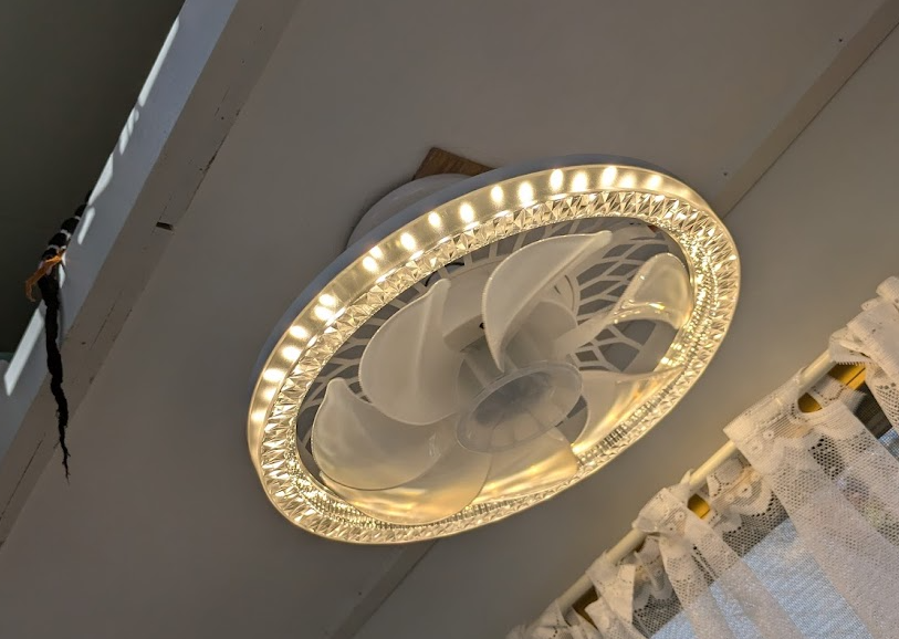
I upgraded the light over the rear bed to an LED light/fan combo. It has a remote, which is obviously intended to be used from below. It throws a LOT of light and the light’s color temperature is adjustable. The fan is nice, though on high, it vibrates a little.
Speaking of fans, I manually wired 12V to the roof vent fan and verified my fears, that as mounted, it was going to pull the screen into the blades and sound like a chainsaw. I fabricated a simple bracket and flipped the fan over. I also flipped the fan blade on the motor so that it could run in the proper direction. The red sharpie arrow no longer applies. 🙂
Since I was playing with 12VDC stuff, I mounted the DC room light.
And the outdoor light, which doesn’t look very bright in full sun, but it is on.
With all these 12 volt devices installed, it was past time to install the massively oversized 12 volt converter, starting with adding a 110V outlet in The Hole.
It will one day be slightly taxed by charging a battery, but for today, 45 amps is about 42 amps more than necessary.
November 1 & 2 was a major IDPA match. It was fun, though I didn’t place or win anything. Coolest logo and match shirt ever, though.
Wifey went to visit friends in Oklahoma on that Saturday and I had plans to continue working on the Jayco and perhaps do some work in the workshop to get ready for some winter blacksmithing.
Trouble arose on the trip home from the match on Saturday. I was only 30 minutes from the range and still an hour from home when my car developed a leak. It leaked oil and connecting rods out of a hole in the side of the engine block.
Luckily for me, this spot on the road was only 20 minutes from where we camp with the Jayco and the incredible people there came to my rescue without hesitation. They loaned me one of their cars to get the rest of the way home. The next morning, I rented a U-Haul tow dolly, returned their car to them then picked up mine and towed it home. At this point, I am still not sure exactly what I am going to do about it, junk it or attempt to repair it.
With the next Love’s Way outing rapidly approaching, we are suddenly in a rush to get a bunch of stuff done in time for the weekend.
I replaced the kitchen faucet and the shower wand and finalized the installation of the water heater, bringing the last of the plumbing to a close.
I added a terminal block specifically to distribute DC power, complete with its own fuse.
I added a light in the ceiling of The Hole.
I added the switch for the roof vent fan to the 12V ceiling light.
Importantly, I installed USB charging outlets by each of the beds!
You recall we had concerns about the transmission on the truck. I had been doing research into the issue and found two solutions, either or both of which could be our problem.
One is a hydraulic pressure regulator solenoid and/or pressure transducer. These are internal parts, but they can be reached by removing the pan on the bottom of the transmission and they are generally not very difficult to replace. There are commonly available parts kits that include the pan gasket and a replacement transmission oil filter, which you have to remove to get to the solenoid anyway, so you may as well replace it. In all, a couple of hours work and 7-8 quarts of fairly expensive automatic transmission fluid. It is unclear if this will directly address the 2nd gear slippage, but it definitely addresses the lack of motion after the truck sits unused for a while.
The other is a far simpler procedure. There is an externally adjustable tension setting for one of the tension bands. It is common for transmissions with 100K or more miles to need this band adjusted. The various YouTube videos describing it’s adjustment call it a 15 minute job, but most of them have the transmission out on a bench or the vehicle up on a lift. They are not being adjusted on the ground by an old fat guy crawling around under the truck. Still, it was not a bad experience overall and the difference is like night and day. The truck shifts like it is supposed to. We can defer the solenoid replacement for now, which is good since for the foreseeable future, the truck is going to be my daily driver.
With that particular thorn out of our toe, we continue working towards the next campout.
I cut and attached a top for the cabinet. It will eventually be painted, but I kind of like the woodgrain. Its just plain old plywood.
We applied this really inexpensive backsplash stuff from the dollar store to the walls around the kitchen. It took some extra effort to stabilize the actual material and to use better glue than it’s self adhesive stuff, but it turned out nice.
We got a nice big holding tank for sewage and I plumbed it for both black and grey water, but long term, we probably won’t leave it this way. Our gray water output will be a lot higher than black water and we may be able to plumb a smaller black water tank directly into that outlet.
We got everything packed up and, while we didn’t leave as early as we had planned, we still got away reasonably early.
Then a new disaster struck.
You know how they tell you to always check your lug nuts before you go on a long trip. Yeah. Do that.
On the same highway where my car threw a rod, just two weeks and eight miles west of where that happened, the last lug bolt came out of one of the Jayco’s wheels.
I failed to get a picture of it before I pulled the wheel out, but it was laying at a weird forward angle, but it had been dragged on the pavement far enough to have a thumb sized hole in the sidewall. It didn’t look like the lug threads in the hub were damaged, so there was hope. I used one of the leveling jacks to jack it up enough to extract the wheel. The spring had obviously dragged as well and we found the gray water adapter half ground, but broken off a few feet behind where we had stopped.
Shortening the story from here greatly, we were able to replace the damaged tire at Walmart and use some standard bolts in order to get the trailer back on the road well enough to make it the rest of the way to Love’s Way, arriving five hours later than planned.
We used two lug bolts and two regular bolts in each wheel. As expected, we had to deflate the tire in order to convince it to fit into the wheelwell, so I am very happy that I threw my inflator in the truck before we left.
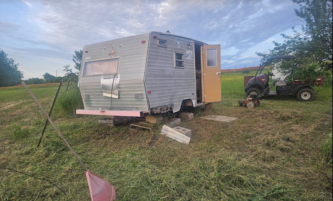
We stopped a couple of times on rest of the trip to recheck the lug bolts, especially since they were in an extra compromised configuration. At one stop, it was easy and comfortable to look around under there and investigate the totally not unexpected lean that the trailer was displaying.
The most obvious thing is that the spring is not connected to the axle, thus the lean. The axle is resting against the frame and the dangling Ubolt will later be found to literally just be hanging there. I am surprised that it stayed there for the whole bumpy trip.
Oh, and the tail lights stopped working. Brake and turn lights work, but no tail lights. The wiring for the lights passes right along the edge of that wall and over that fender, so it may have been damaged.
I did a lot of shopping online for replacement Ubolts and tie plates and later springs. It occurred to me that not only would it be wise to replace the spring because it would be prone to break where it got ground to smithereens, but the camper has always ridden really low and some new springs might lift it up a bit and help with the sewer connections and towing into driveways and all those kinds of things. Once I had some pretty good ideas on what to get, we also checked some local(ish) places and found what turned out to be arguably the best deal. I got two new springs that are a little heavier, new Ubolts and tie plates, all for $133, no waiting, no shipping. I did have to drive into Fort Worth to pick them up, but no biggie. I also procured 10 lug bolts, so it will get all new bolts and we will have 6 spares 🙂
We are planning to go install all this on Saturday and probably haul the camper back home for the rest of the work, like replacing the broken gray water fitting and other damage done in this excursion, besides the other pending work, such as installing a battery, replacing the seals in the toilet, finishing the interior trim.
So in just about exactly 30 days, I was laid off work, had my car blow up and nearly destroyed the camper. The one shining star is that just today, I got a really good bite on a job application, something similar to what I was doing and for similar pay. With a little luck, I will ace the interview and put a lot of this negative stuff behind us!
As I often do, this first post is a massive catch-up post, covering months of work and events, intended to bring the reader up to the present day. I apologize, but such is the nature of the blogging beast, at least when I do it.
Way back in 2004 or so, we picked up a very cute 1972 Jayco Jaywren camper.
The guy we bought it from was a crop duster and among other customizations, he had painted a Texas flag on the roof so that he could find it easily from the air.
It had some minor water damage from leaks around the marker lights. After using the camper a couple of times, we tackled repairing the worst of it, where the front marker lights had leaked and damaged the front wall, mostly above the window.
There was also quite a bit of damage at the front corners, also largely from the the corner marker lights leaking.
The repair came out pretty ok, other than some difficulty matching the color. The luan plywood we used and the pecan stain looks redder in these nighttime flash pictures than it did in person, though it was obviously not the factory paneling.
We continued using that camper for a number of years, though it did go through some fairly long periods of storage.
Among other hobbies, I am a ham radio operator. There is an big annual contest in the USA called ARRL Field Day, wherein you try to contact as many unique operators as possible during a 24 hour period, preferably under simulated emergency conditions. There are points mulitpliers for teams, using emergency power, remote operations, etc. In 2014, a friend of ours had her large RV stored on our property, so I used it as a base for operating at home under generator power. It got me out of the unairconditioned workshop for the contest, which turned out extra helpful since I threw my back out during preparations.
When 2015 Field Day came around, the big RV had returned to it’s home, so I thought I can just duplicate the conditions using our little Jayco. I towed it over from the other side of the property where we store it to a spot outside the workshop. I got it roughly leveled and stabilized and I opened the door to get started setting up. This is what I saw:
That is hundreds of dead bees. They were everywhere. Long story short, turns out there was a large hive in one of the storage hutches. The beekeeper we had come to remove the hive said that these bees managed to slip out into the camper proper and were unable to find their way back home and probably perished in the heat.
In any case, I made other plans for 2015 Field Day.
It continued to be used occasionally but rarely until summer of 2019. We have a friend who is may be best described as a vagabond. He visits various friends all over the country for a while every few years and while visiting each place, he generally tackles some projects, presumably to help offset the costs of hosting him. He is a talented carpenter and really quite the pantologist. There is a catch. Ya gotta let him do it his way. This has lead to more than one clash, generally over materials and scheduling. For example, we might want to get as much material as possible to leverage a credit card discount for a large purchase, but he’s not ready for that material and doesn’t want to even think about the project that far ahead yet.
[Editor’s Note – April 2026] Our friend was staying at a home, doing what he always does, probably repairing and refurbishing something around the property for someone, always exhibiting excellent skills while simultaneously being absolutely exasperating. Sadly and somewhat surprisingly, he perished in a shed fire in March of 2026. By all appearances, he saw (or possibly started) the fire, warned the resident of the house and was probably trying to extinguish it or save something. By all appearances, he was overcome by smoke and fell in the doorway of the building and that is where they found him. Regardless of our own exasperation with some of his ways, he was still loved. We had kept in touch in the years since the last time he stayed with us, and for that I am thankful.
Knowing all this, we still asked him to address some water damage on the Jayco, similar to the damage I had fixed some years ago, but in the back and the ceiling. We didn’t expect it to be simple, but we didn’t expect so much of the RV’s complete intrinsic value to be destroyed in the process.
He had gutted it, far more than necessary for the areas we wanted to address. His plans for the remodel apparently involved permanently removing the shower and kitchen as well.
So, being the optimist I am, a few good things came out of this process. About half of the aluminum skin got an above average paint job. A lot (though importantly, not all) of the original water damage was addressed. Some arguably weak parts of the structure were redesigned stronger.
On the other hand…
I don’t recall the exact sequence of events, nor do I want to relive them, but long story short, the RV project was buttoned up unfinished and our friend left on somewhat tense terms, not entirely due to the RV project alone. He has not been back, but we keep in touch. His somewhat hard life may be catching up with him, as his health is not fantastic. When he one day reads this, I hope it finds him well and, even though we may have cursed his name a few times during the project that follows, he still got it started.
The main thing is that some decisions he made have had long lasting consequences, not all of them great. Sometimes, I can see where he was going with something or why he may have done this or that. Other times, I can’t help but think, what the hell was he thinking? I’ll try to not dwell on them too much, but I can’t promise to never let any irritation come through. I’ll call him Bob.
[Editor: As mentioned above, “Bob” has since died. I think it would be dishonest to remove or edit my Bob comments from this point forward. I also think that he would agree]
The general disgust with the whole situation caused us to let the poor thing sit untouched for about 5 years. Sure, checked inside every once in a while. It was apparently sealed up well enough to keep the wasps out, but it did accrue more unseen water damage during that time. I mowed and weeded around it since Bob took the f*%kin’ wheels off it and I couldn’t move it.
Without going too far off on a tangent, we have a place where we like to camp at least once a month. We took our little motorcycle camper up there once and due to it blowing up tires just before we arrived, we ended up leaving it there and building a permanent campsite on that property.
The little camper is a clever design, especially for setting up a place for two (plus pups) to sleep, with attached storage/closet space in a package that was small enough to tow behind a large motorcycle.
What it is not is handy. It takes at minimum an hour to get the whole thing set up with the front porch tent and the beds made up, etc. Also, it is so compact that we have to pack in just about everything. There is essentially zero storage within that camper.
So, we were inspired to assess and possibly refurbish the Jayco into appropriate condition to haul to this property to replace the clever but pain in the butt camper.
May 10, 2024
It had been a while since the last weeding around it, so that had to be task one.
Some of the worst deterioration over the last 5 years is clearly visible here, the lower panel of the skin had come loose, leaving the plywood completely exposed.
I didn’t want to work on it way out there where it was parked, but rather much closer to either the house of the workshop, where power and tool storage would be much more convenient. We decided to park it in the driveway for easy access to the garage and power. However, to move it, we were going to need to put the wheels back on first.
I will never, under any circumstances, understand why Bob felt the need to remove the wheels in order to work on water damage on the roof. Now, I know that part of what he was doing was refurbishing the rims, which is somewhat better done with the tires removed. On the other hand, it’s been 5 years now, so they need to be painted again. Sigh.
On the other hand, Bob is no idiot. As you can see, the wheel hub is covered with a plastic bucket and beneath said bucket, the axle is wrapped in a grease soaked rag. New bearings and seals were filed away in a coffee can inside the trailer. The only thing I could not find was replacement cotter pins.
The tires turned out to be a mildly nasty surprise. The date code on the existing low mileage tires made them old enough that Discount Tire would not even mount them, even though they were probably fine. We ended up buying a new pair of tires, but since we knew we were planning to tow it nearly 100 miles as soon as it was ready, we considered that the safer option anyway.
Remounting the wheels was a challenge. I recall changing a tire for some reason years ago on this RV. The driver side tire just will not fit up in there without heavy duty mechanical assistance. I ended up having to deflate it almost entirely so that I could squeeze it between the axle and the body of the trailer.
Upon close observation, I think the axle is very slightly off center towards that side, making the gap too small for the full width radial tire to fit between the axle and the fender.
But, perseverance won out.
I set it up in the driveway, reasonably close to the edge.
Next, I had to transform it from a box stuffed with parts and trash…..
… into a blank canvas!
The first major challenge was the floor. The plan to to put down vinyl tile. The original flooring had been linoleum. My favorite solution would have been some form of laminate flooring, but there is a 10-15 degree upsweep at the back which would have been a significant challenge with any rigid flooring.
Multiplying the challenge was that Bob had applied Thompson’s water seal to the floor. This is one of those things where I can kinda see where he was going; it’s an RV, it’s likely to get water in it sometime, so let’s help keep the floor from rotting. On the other hand, Thompson’s is an oil based product. It is not adhesive friendly. Furthermore, there were some thin remnants of linoleum still left on the floor, sealed down with Thompson’s. We killed an entire weekend doing nothing but scraping and power sanding the floor in an attempt to get through enough of the seal to give the primer and floor adhesive a chance to stick.
May 21, 2024:
The floor turned out pretty nice, though.
Later, about 10% of these tiles would need to be pulled up and reglued with Liquid Nails, but that was just mildly irritating.
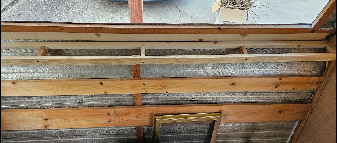
The next major step was to repanel the ceiling. Although *technically*, the entire ceiling wasn’t trashed, enough of it was for it to make sense to replace it all.
Insulation was a significant challenge. The “joists” in the ceiling are essentially flat 1×2 lumber, so there is about 3/4″ of space for insulation. What turned out to work the best was taking standard insulation batting, splitting it down really thin, about 1″ to 1-1/2″ then stapling that to the wood as one normally would. The split off pieces were saved for use in the walls, where it was easier to get by without the kraft paper.
We used a lot of 5mm plywood, from either of two sources. Lowes has a very light colored poplar plywood that runs about $26 per sheet as of this writing. Lowes has the advantage of being about 20 minutes away and since we didn’t want to store a gob of material ahead of time, it was a reasonable compromise. This stuff takes paint pretty well.
June 8, 2024:
The first sheet was essentially 7 x 4 feet with no weird cuts. We had decided on a light green color for the ceiling and eventually the cabinet doors and drawer fronts, partly because it was inexpensive and readily available from Walmart.
The next ceiling panel was decidely NOT simple to cut. I do wish that I had cut it a little closer around the roof vent, though. It would, however, be nearly four months later before I would realize that.
It is amazing that this panel fits at all, let alone on the first attempt:
One more small piece at the front of the trailer and the ceiling is nearly complete. A few months later and I would end up replacing that last piece with a wider one, having changed my mind about how I was going to finish out the corners of the ceiling at the front and back.
The next major task was to repair all the walls. Bob had done the street side wall, or at least most of it. I would need to fix either some old damage that had never been addressed or new damage that had appeared in the 5 years that the Jayco sat partially done. Considering the advanced rust in the staples and screws, I’m pretty sure most of it was really old water damage.
I digress.
I have fewer in-progress pictures of this process than I would prefer. Some of this work was fun-challenging and some of it was exasperating-challenging.
The framing in any RV is, shall we say, least effort. In the factory, they butt 1×2 lumber together and drive heavy duty staples across the joint, usually on both sides.
Then paneling is attached on the inside and the aluminum skin to the outside and the assembly is reasonably rigid.
We don’t have these monster staples available to us, short of literally hammering used staples back in. The material is too thin for most other decent joinery, so we have to innovate. I’ll give Bob full credit for starting this trend, though I’ve done enough of them to feel I’m better at them by now. 🙂 I’m not sure what this joinery is called, officially. It’s not entirely unlike dovetails, except there is no actual dovetail. We basically cut a notch in one board, closely fitted to the end of another board, then use glue and sometimes screws or crown staples to secure it. It’s dovetail adjacent.
In short, I used the CRAP outta this joint to reinforce, repair and replace lumber all over the Jayco, but especially in the walls, because they are all built like this, flat 1×2 lumber in essentially a 2D assembly.
Sometimes, I felt an existing structure needed more material. I added the center vertical bracing here to help make this particular panel more rigid. This area had the original gas powered refrigerator and gas furnace that came with the RV from the factory, but both were gone long before we got it. I have plugged those holes with 16ga sheet metal and I think the extra framework will help keep all all that together.
June 15, 2024:
I have used a 2×4 sheet of 3/4″ plywood on the bed of the Mule as a workbench for years. It is a good working height and easily adjusted. It works really well.
That makes removing an entire wall and repairing and replacing pieces from there generally the easiest.
This is the top half of the rear wall. The opening to the left of the clamp is where the window goes.
The finished wall, back in place on the camper, with poplar plywood on the inside:
The framing above the shower was a difficult repair. The parts of the curbside wall that are missing were so rotted that they crumbled, so there was nothing to get any good measurements off of. The frame pieces attached to the roof were in pretty poor shape as well. As of this writing, this area is put together, but it still needs some rework and adjustments because my best guesses as to where to cut and add framing were not great. Plus, Bob’s wall on the other side is about 3/4″ too wide.
The actual work came together pretty well, though. It’s like Hubble, nicely built to the wrong dimensions 🙂
It was about this time that I began to realize that this work is not so much carpentry as sculpture. No two dimensions are the same, every cut is custom, whether a custom length or custom angle. This is what sculpters do.
We decided to use OSB for this particular piece of wall. Unlike all the other pieces of wall, it will never be seen, so the rationale is why spend $30 on a sheet of nice plywood for that? If I had it to over, I would go for the regular plywood. The OSB is thicker, heavier and generally just harder to work with than the plywood, for not that much savings. It worked out fine, it was just more of a pain than it probably needed to be.
One reason this piece was difficult to work with was because I could not really remove this wall frame. The shower, the kitchen cabinets and the door are all attached to this frame. Furthermore, I was going to have to depend on Liquid Nail for most of the attachment because I could not get behind the sheet to drive screws or staples through the OSB into the frame. Thus fitting it was a process that involved a LOT of putting the sheet up there, supported by the jacks, mark a couple of things, pull the sheet out, make some trim cuts, repeat, until it fit reasonably well.
Though I don’t appear to have any in progress pictures, the entire bottom half of the rear wall was essentially built from scratch. Where the old window air conditioner had been cut in allowed a lot of water in and the street side rear corner had its own leaks, so the original wall was pretty much kindling. The completed new wall is in place here, though we will be back for an issue.
It is now a little after 7PM, June 17, a Monday.
I have just finished the OSB wall. My wife has gone out of town for a few days and we realize that storms are expected on Tuesday. I need to button up this whole thing that I have been able to leave open for a few weeks. I need it to be reasonably rain tight.
I have had the skin on and off the camper enough times to be good at it, but this is the first time the rear skin has gone back on with all these new walls back here. By 9PM, I have the skins back on, but if you look closely, you can see that I needed to use foil tape to fill in an area at the top corner. That is where the shower framing I mentioned earlier is no longer the same shape as the outer skin.
By 12:30 Tuesday morning, I have installed the windows that I can; the shower window is not ready to go in yet. I have the old air conditioner hole covered and taped and I have door installed.
The door was a significant challenge. At the time I was ready to put the door on, which is not really a task for one person, the wind had moved in. The wind had already made dealing with the large flat lightweight pieces of aluminum skin a massive pain. The door was just that much more of a problem child.
When putting the door in by oneself, you need to be able to grip it well enough to lift the entire assembly, often by only a fraction of an inch, but it must be done. To get a reasonable grip on the frame, I had to have the door ajar. A gust of wind ripped the open door from my grip. Though I did not drop the door, the force slammed it hard enough to spring the bottom of the door itself open and wrench the frame out of square. I suspected there was damage there anyway, this just proved that there was little holding the door together down there, and even less now.
The wind subsided enough for me to gather the door up onto the Mule worksurface and get it beaten into shape enough to close again and I managed to get it mounted.
My door breaking gust turns out to have been the peak wind of the evening, 36mph, shortly before midnight.
The sad irony is that, by the time I buttoned up the whole camper and put away all the tools, it was well after 2AM. I was exhausted for work the next day.
It never rained.
June 24, 2024:
I have a TIG welder. I am reasonably good at welding steel with it. I chose the Primeweld 225X based largely on this pretty old review. It was not old when I first saw it and a few years later when I was ready to buy my welder, the 225X is still well reviewed, so I’m pretty happy I got it. I quickly learned to weld steel with it and, especially compared to my 15 year old Harbor Freight MIG welder, it is SO clean.
One of my TIG welder’s many talents is AC TIG, which is what you need for welding aluminum. I say the welder’s talent because, at this point anyway, it is not on my list of talents. I found I can put down reasonably OK practice beads on a aluminum coupons.
That does not translate directly be being able to repair the camper door frame. Oh, I guess I can say that it’s more assembled than it used to be. This is the best one:
It was really easy to blow through.
I know now that I probably had the AC balance too far into “cleaning”, which made me crank up the amps trying to get a pool, then it was really easy to get too many amps and smoke it.
Practice.
In any case, the frame is arguably better than it was. Bad welds are at least slightly better than open cracks.
june 30, 2024:
I’m back to the kitchen wall.
Regardless of the poor condition of the plywood, the framing in this area has survived pretty well.
I didn’t realize at the time I was doing this work that the two copper lines on the left were deprecated water lines or I would have removed them. The one copper line on the right is the propane line to the range/oven.
Though I had high hopes of replacing this plywood in one piece, it was not to be. There is an upper and a lower piece, but they turned out great!
Next was to replace the 3/4″ plywood at the bottom of the wall. This is somewhat structural. In the factory, I suspect this piece was first and everything was built toward the inside from it. That is not really an option here.
Once cut to size and the wheel well is cut out….
Next comes more ersatz joinery.
Then even more joinery as I cut in and frame around the shower window. Still no way to use any fasteners, so relying heavily on Liquid Nails and clamps.
By this time, I have partially addressed the mismatch in the corner, but it still requires some special procedures to keep it rain tight.
The plan is to replace that top section of skin with material salvaged from another camper we have. It won’t match exactly, but it will look better than this bandage.
July 4, 2024:
I finally get to start playing with some of the wiring. I have run some marker lights at this point, but this is the first real work on the 110V systems.
I have neglected to mention… I picked up an oscillating multitool and it has been invaluable for the cut-in joinery and things like cutting a shallow slot for the wire to route through. It has metal cutting blades available and they make pretty short work of nails, but I have discovered that screws are significantly tougher stuff.
This particular wire goes up through the ceiling and drops out over the bed at the front of the camper. The orange wire goes to the utility box where the breaker panel will eventually be. Originally, the wiring went the other way, from the breaker, up the front wall to that light, then to here to power the refrigerator.
The utility box or closet, we usually just called The Hole, needed to built back from scratch. I don’t have any interior view pictures of what it used to look like, but I recall that it had a few cubbyhole shelves where the jacks could fit. I’m not sure if I will replicate those or not, but I definitely gotta start somewhere.
The original framing was gone, but Bob had a start on the replacement, so I was able to cut in the rest of it fairly easily. The rest would need to wait.
In the condition shown here, the key would not hold the door shut, so I felt obligated to tape it shut to keep out water.
In finishing out the back wall, I discovered a measurement error I had made on one of the braces. That brace was one 1×2 width off, making it difficult to secure that wall because that brace was floating where there was nothing to screw it to.
I pulled that piece of the wall out and joined in a sister to that brace.
Except that I missed and joined a sister to the wrong board (red arrow) and had to do it a second time (green arrow)!
July 12, 2024:
Bob had replaced some fairly complex pieces on the front of the trailer with 3/4″ plywood, but it wasn’t really well protected against the weather, so in 5 years, these plywood pieces already needed replacing.
I used similar joinery to keep it strong.
For what I am sure are reasons, the two sides are not the same.
With those plywood pieces in place, I was finally at a point where I could start installing interior paneling. The first panel would be a fitting challenge.
I didnt have a panel square, but it was pretty easy to knock out a reasonable homebrew version. I still use this on occasion, but I have had to shorten it for a task.
July 20, 2024:
There are so many angles and intersections that it takes a lot test fitting and trimming to get the piece up there, plus even though I drew it as a line on the measurement sheet, that top edge is actually a curve. In any case, success!
Next came a ton of small but important jobs replacing damaged paneling, like the bottom fo the kitchen cabinet…
…and below the shower door.
August 9, 2024:
I’m about to leave for a week for the IDPA National Championship match in Alabama, so there is a push to get some stuff done and to seal up in case it rains while I’m gone.
It is difficult to show exactly what is going on here, but I am replicating the narrow shelf that was at the front of the trailer under the window. This shelf is only about 5-6 inches wide and serves as the transition between the angle between the upper wall and the lower wall. As such, it was the first time in this project I needed to deal with a specific angle other than matching a panel.
As it turns out, the top edge of that front 1×2 is cut to 15 degrees and I will find that 15 degree angle is repeated often in the camper, so yay!
It is a long span, so it needs some braces.
In building the utility box, the 15 degree angle persists, though here it is more obvious as 15 degrees off of 90, or 75 degrees included.
One really irritating part about this entire project is how sometimes a dimension will sneak up and bite you on the ass. Throughout the construction of the rear walls, I carefully maintained the relationship between the old wall and side wall that Bob built. His was was maybe overbuilt, the lower half being made of 3/4″ pine lumber rather than the 1×2 framing that the rest of the wall was made from. Generally, I’m good with that. I am not sure exactly how it happened but somewhere in that process, the rear wall assembly ended up about 3/4″ wider than the aluminum skin, but only at the bottom. I presume that is on me. Maybe the wall I built is square and shouldn’t be. In any case, it had lead me to a janky solution wherein I have to fill a gap in the skin.
By the time the trim is in place, it’s kinda hidden.
August 24, 2024:
I’m back from Alabama and dealing with COVID 19 that I presume I picked up there. I’ve managed to avoid it for five years, but finally did not dodge it this time. Here’s a tip. Paxlovid gives you diarrhea. Don’t forget to replace your electrolytes while you rehydrate. I very nearly collapsed before it occurred to me that I simply needed Gatorade. Half an hour later, I was golden.
In the front end of the camper, the original configuration had a dinette that would convert to a bed.
We were planning for just a bed in place of the dinette. We experimented with some rollaway beds we used to use for some specialized camping we did a million years ago and one of those fits here.
They have always been pretty compromised sleeping options, however. This mattress has inner springs, but it is terrible. The combination that worked best when we used them often was a piece of plywood sized to fit inside the frame’s springs, this mattress, then a four inch foam topper. Even so, we can do better and found this piece of actual furniture that is slightly bigger but still fits in the space.
It needed a little TLC, tightening joints, etc, but it is going to work great.
I continued with insulation and paneling.
We got new paneling from Plywood of Fort Worth. Had we gotten this plywood from the beginning, we would probably have gone for a stained wood finish instead of paint. It’s a pity to cover up this pretty wood with paint.
On or about July 8, there was the first mishap with the EasyUp shade. We rushed home trying to beat a storm to take down the shade and perform other storm preparations. We arrived just as a burst of wind also arrived, which pulled the shade out of our hands, flipping it up and over the camper. The roof vent was open, so the frame of the shade caught on it and bent the vent lid pretty badly. I was able to close it from the inside, but only just.
August 31, 2024:
I got a replacement vent lid and since I was in there anyway, I decided to add a fan to the vent. A 40 thousandths welding filler rod makes a decent wire fish.
Meanwhile, the paneling continues whenever possible. I REALLY wish we were staining this.
There is one occasion when the decision to paint helped hide an otherwise egregious error. This panel was almost but not quite square. After fitting, I pulled it down to cut in the hole for the outlet and managed to get it turned 90 degrees one direction or the other. Luckily, between paint covering the grain and trim covering the gap up top, I got away without having to trash the piece.
September 6, 2024:
The parts for the original rear bed are still around.
Under this bed is where the water heater lives. I am not sure if Bob had more in mind for this area or not, but the ledge he built on the wall that appears to be for the bed was not high enough to clear the water heater fittings, especially with the lines attached. I added a fussy cut 1×4 to add both vertical height and strength. Later, I would have to add even a little more.
The front frame for this cabinet/bed was in sad shape, but after I got started on it, I realized that I could salvage most of the actual framework and that the paneling was the worst part. There were about 1.6 million tiny staples holding the paneling on the frame.
Here is the assembly in at least good enough condition to sit on.
While I continue with more construction oriented tasks, Wifey has gotten a great start on painting. In this particular panel, note that a decision was made to use the material I had rather than wait and buy a new piece of plywood. This strip at the bottom will be obscured by the cabinet *and* by paint. Compromise is ok sometimes.
If I recall correctly, these were the last full panels to go in. Yes, those gaps are bigger than I wanted.
September 21, 2024:
By the time the back bed, the front bed and the cabinet were all in place, there was a very tight fit and I had a weird little gap to fill. To accomplish that, I needed to remove a panel’s thickness of frame from the rear bed.
Once that was completed and the top finished out, the bed platform works out pretty well.
The entire bed is in good shape, other than needing a coat of paint.
The portable air conditioner we got works well, other than drawing more power than the outlet in the garage can adequately provide. I’ve been running it on my generator when needed. The long term plan is to build a platform for it to sit on at the back and vent it out the back wall.
September 28, 2024:
I skipped a lot of photo opportunities with the electrical panel, but it is done. This is the original two circuit panel, but I have equipped it with two dual circuit breakers to let me break up the loads into four circuits.
I need to add an outlet in the utility box for the 12V converter. I will probably put it on the refrigerator circuit, which is arguably the lightest single load.
The other side of the utility box has the DC wiring, which is mostly tail lights and marker lights, but importantly, a circuit for the 12V lighting and that one fan I added for the roof vent.
October 6, 2024:
The original camper had cabinets everywhere, but as most of those are either damaged beyond reasonable use or were designed to be used with other cabinets or elements which are no longer there, we have elected to use shelves as storage. The cabinets also likely added to the rigidity of the structure, so the shelves have that in mind as well.
The front shelf went through a couple of design and build iterations until we arrived at a suitable size.
The shelves needed to integrate fairly well with the trim, so they went in and out during the process. In the end, I am pretty happy withe shelves and semi-happy with the trim
October 10, 2024:
While I was working on the shelves, we had a combination of events. I typically tie a couple of the legs of the EasyUp shade to something, but we had been moving stuff around and using those things and the shade ended up not particularly well secured when we had some gusty winds come around.
The thing landed upright with one slightly bent leg. I was able to straighten the leg and we were able to set it back up and use it. For 6 more days.
Finally having all of these pieces in at the same time revealed how little room there was for this bathroom vanity turned utility cabinet in this space.
October 13, 2024:
We knew from the time of purchase that the left drawer of the bed pedestal would be inaccessible, but now that everything is tucked in here, the cabinet is truly an interference fit in that space. You have to lift the cabinet to put the bed in.
We had contemplated it before, but now it was time to either abandon the cabinet or chop it in half. The way it is made, it was not bad to cut it in half, keeping the left side. It was easier than expected, really. The operation took about an hour.
An oddball piece of the aluminum skin that fits in front of the curbside wheelwell and under the door was misplaced for a while. Interestingly enough, the full size cabinet does not fit through the door frame, so to remove it to split it in half, I needed to remove the door frame. While the door was off, I installed the long lost piece of skin and a missing piece of wood needed for it.
There was also the end cap panel of the kitchen cabinet that I could replace while the door frame was out. It had been painted, but the paint was not adhering well. This panel also has an aftermarket switch installed for a 110V porch light. I have never liked that this switch is mounted sideways and crooked at that, so I also replaced that panel and moved the switch box at the same time. I also upgraded it to a dual switch, the idea being that we could turn on an inside light on the way in the door as well.
However, I did not account for how far into the opening the door frame protrudes. Now I need to remove the door again in order to wire up the switches.
The platform/riser for the air conditioner is completed. It’s base is at, say it with me, a 15 degree angle. It also hides and protects some the plumbing.
I added rails to help keep things from rolling off of it and of course, a coat of paint. With colder weather coming soon, we have put a heater in its place for now.
With less pantry space now, every extra bit of storage is helpful. Ikea to the rescue!
Now that we are getting really close to completing the project, Wifey can really crank up the decorating skills This is the front bed; very cozy.
October 16, 2024:
As promised, 6 days later, the wind strikes again. Fate is watching and knows when you have left something unsecured.
This time, the same leg that previously was just bent is now almost completely severed. It is essentially trash now. I am just very happy (and lucky) that it did not damage the CanAm.
October 17, 2024:
We are now just a couple of days from what we hope will be the debut, towing the camper to Love’s Way for a shakedown cruise and overnight camp, then bring it back home to continue working on it. To that end, we have begun working on stuff required for that trip, like tail lights.
These are actually intended for a boat trailer, which means they are intended to bolt to an open frame. Maybe not the best design for me to use here, but I made it work.
Also, I replaced the plastic cover over the old air conditioner cutout with a sheet of aluminum that we had purchased for the purpose a couple of months ago. Weather sealing is via butyl tape.
October 18, 2024:
The tail lights need a connection to the tow vehicle. The wire I picked up at Tractor Supply or Bomgaar’s, I forget which, was cleverly arranged for wiring a flatbed trailer, with a short white ground wire, then a yellow/brown pair for the left tail/marker lights and a green/brown pair for the right. For my wiring, I extended the white ground to my terminal strip and bonded the two browns together.
FYI, the black/white wires on the left go to the electric brakes, which are not currently in use and the red/brown wires is 12V DC to the 12V lighting and the vent fan inside the trailer. These will be connected to the converter and battery at some point soon. Not today.
I failed to take pictures of a LOT of work involved in getting the plumbing kinda working. There was a slight leak on one of the hot water pipes, easy to fix. Then the temperature pressure relief valve on the water heater itself was the next leak. To test what I could, I bypassed the water heater and got water flowing to the kitchen sink.
The grey water drain seems to be ok, too. There is something amiss with the faucet itself, though. Whenever it is open, water drips under the counter. We have a replacement for it anyway, so it’s not a big concern, just something that we were already going to do later.
Sometimes, little things are very important. This chandelier is one such thing. I added a pull chain switch to it and this was the first interior light completed.
The vent hood and kitchen light were the next to complete.
At some point, this light will be connected to one of those two switches next to the door.
The vent hood suffered some rust during the 5 year storage wait. We will be repainting it, but for the debut we decided that sanded spots were much better than rusted spots. We also need to find an appliance size bulb to fit in there. A standard bulb may be too large. At this point, the vent to the outside is still sealed up, but we don’t need the ventilation just yet.
The final interior light is the one over the rear bed. You may also notice all the curtains are now in place. I don’t think I have mentioned those as yet.
There was so much that we had to finish up that I didn’t bother to take pictures of. The bathroom door got remounted, rugs put in, curtains hung, beds made and remade, cabinets secured, wires tied down, skin stapled down, the oversize cotter pins in the wheels replaced and the hubcaps installed, tire pressure adjusted, 5 months of debris cleared from the driveway. A few days earlier, we even put new tires on the truck. In all, we worked until 3AM Saturday morning….
October 19, 2024:
… which made our plan to leave by 11AM difficult to achieve.
We left about 5:30PM.
Other than arriving later than we wanted, everything worked fine and we slept like royalty.
We have a few things to work on, like the cabinet that was originally a bathroom cabinet does not know how to keep it’s drawers shut in an RV. The chandelier lost one of it’s dangly bits, but not until the trip home.
So, there you have it. 160 days of almost daily sculpting, but especially weekends. There have been some days off, even a week here or there. Weather has been remarkably cooperative, rain-wise. Then again, we haven’t really tested for leaks, have we?
The list of things remaining is still a long list, but generally none of the items are what I would call Major Items. Nothing big left to build, but a lot of things left to do regardless.
Plus, while it was extremely maddening while it was happening, it was actually resolved pretty quickly and could have been resolved three different ways. Really, other than its temporary effect, I probably shouldn’t say anything.
Before all that happened, I had been slowly resolving little issues bit by bit.
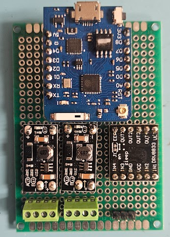
I have assembled what might be V1.0 of the Activator hardware board. The Trigger hardware board will probably be very similar, if not identical. Really, identical board with different software could be ideal.
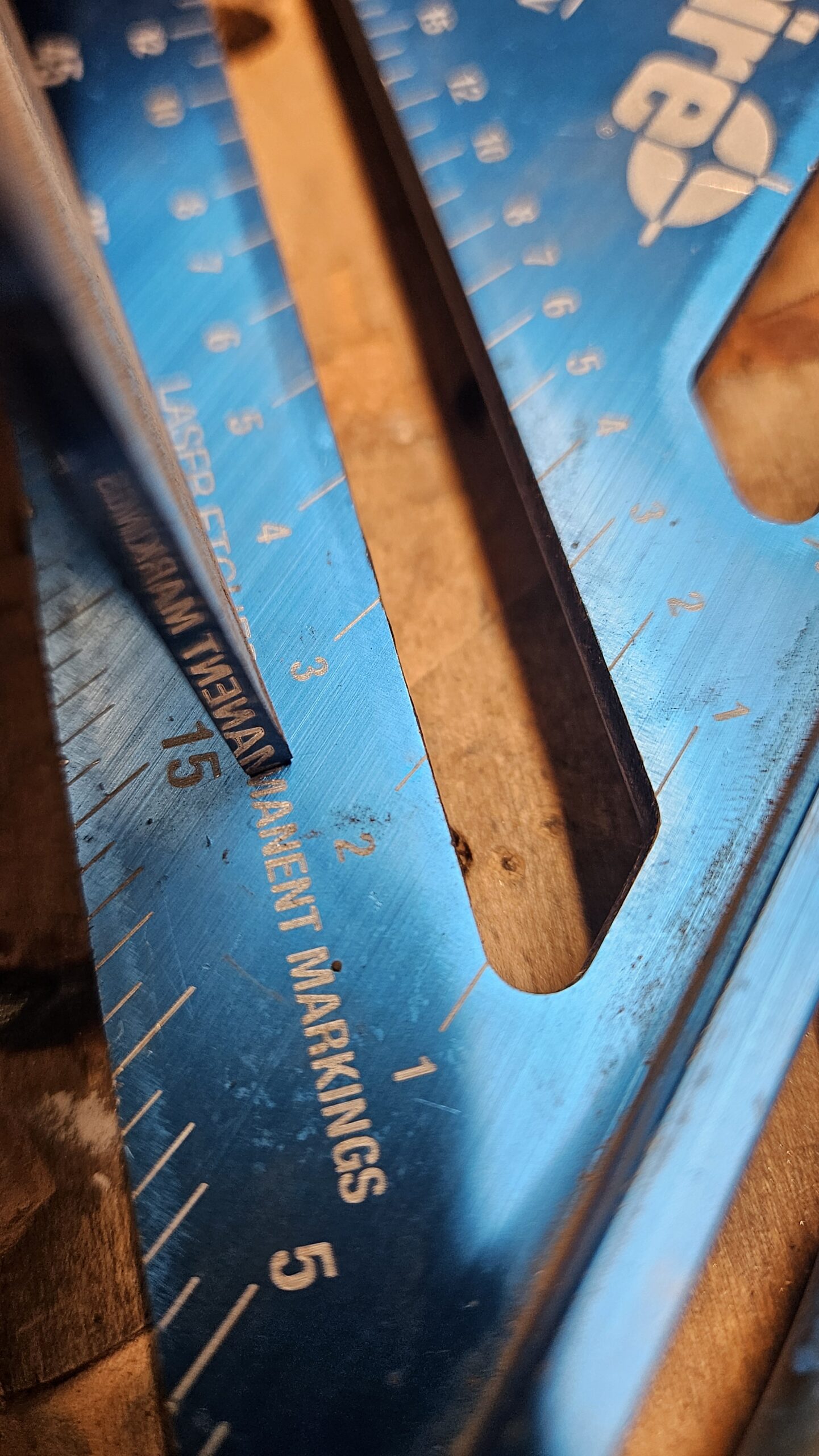
I say might because I find that I do not care for these particular green terminal strips. When I ordered them, I was expecting larger units. There is not a good sense of scale here, but these are eyeglasses sized screws. Actually, you can see that the screws are about the same size as the solder pads on the circuit board, which are about 0.075″ in diameter. I have already cross threaded one by opening it too far.
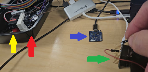
Otherwise, from left the right, the first terminal strip is for the battery negative and positive and the external power switch. The next strip is for the plunger reset warning light and the plunger sensor switch. The three pin header is for the servo that trips the plunger.
Above the connectors, left to right are the 5 volt regulator to run the controller, the 12 volt regulator to run the warning light and possible future things and a dual H-bridge board that currently drives just the warning light.
Finally, above that is the star of the show, a clone of the unbiquitous Wemos D1 Mini Pro, so called Pro because it has an external antenna connector, which will be handy since this board will be inside a steel box.
I had two power mishaps with this board. Really, it was one power mishap that caused two problems.
When I was researching what equipment to shoehorn into this system to implement wireless, I had some realizations that could be visualized like rungs on a ladder. First, I knew that my controller board was necessarily going to have to take up some space and my Activator device is pretty crowded inside already.
One step up on the ladder.
The industrial relay that protects the lock motor, while a very robust device, is at it’s heart a very simple device that takes to continuous power from outside and limits it to a short half second or so pulse to the lock motor. I will be providing that lock motor power locally now, through my controller board, which is smart and can do the time limit function. The industrial relay is also pretty big, so removing it might be enough for both my controller and the battery.
Next step up on the ladder.
The lock motor runs on 12 volts. I did some measurments and found that during it’s brief moment of activation, it pulls about 4 amps. If I limit it to less than about 3 amps, it doesn’t pull hard enough to reliably trip the plunger. That is not a terrible amount of current, but as I look around for commerical off the shelf 12V 4A lithium batteries with easy connections and easy charging solutions, they all tend to be kinda big. Way bigger than the space vacated by the timer relay, leaving no space for the controller board. Batteries of other chemistries are even bigger and don’t work as well, so I didn’t even look.
DC to DC boost converters are thing these days. Actually, I have had a really successful history with multivoltage DC to DC converters back in my robotics days. Unfortunately, those blogs were lost ages ago. Anyway, I shop for converters and in a field absolutely flooded with converters for 12 volts INPUT, the few that I could find with 12V output tended to be physically large multivoltage output units for 48V+ input or if they are boost converters that work at smaller inputs, they are never more than 1A out. There are a few exceptions in the $50 range and I really want to avoid those if I can.
I did play with the *voltage* on the car lock and found that, so long as it had plenty of current available, it would reliably work all the way down to just under 6 volts. 7.4 volt LiPO batteries are common and RC car batteries have commonly available connectors and chargers. I found some reasonably high Ah rated batteries and a nice charger that wasn’t stupid expensive and got them on the way, along with some appropriate connectors.
Next step up on the ladder.
Next, I knew I needed to power the controller. I have a couple of options. I can power it from the USB jack with a converter connected to the battery, but it seems more elegant and controllable to supply 5 volts to it externally. I have batteries coming and I did find some nice 5V 1A DC-DC converters in my earlier shopping, so I found them again and ordered a handful. They came in a package of 10, very inexpensive.
Next step up on the ladder.
Big epiphany, with the controller board, I can directly operate a servo! This eliminates the need to ‘protect’ the lock motor and a servo is significantly smaller than the lock motor. I can power it directly from the board or even directly from the battery if the 5V 1A supply is not enough. That will also ensure I have more room for my RC car battery.
Next step up on the ladder.
I had tested the nice big warning light that I want to put on the Activator to remind people to reset it. At the time I chose this one, everything was running on 12 volts, so it made sense to get 12 volt lights. I got a variety of colors. I particularly expect to use red for the Activator light and red, yellow and green on the Control Box. Experimentally, I connected a red light to 7.4 volts from my bench power supply. It lights up, but not very brightly. It will almost certainly be hard to see outside even at full brightness. I need 12 volts for at least the light. Luckily, the same DC-DC converters I ordered above are actually adjustable for 5, 8, 9 or 12 volts output, so other than having to add it to the board, problem solved.
Next step up on the ladder.
This week, I had some time to tinker and got the board built and populated. I don’t think I connected power to it before verifying the power, but more on that in a minute. With the controller board out, I connected one of my batteries and found that the 5V board was outputting 7.9 volts. The 12V board was good, but 7.9V is not 5V.
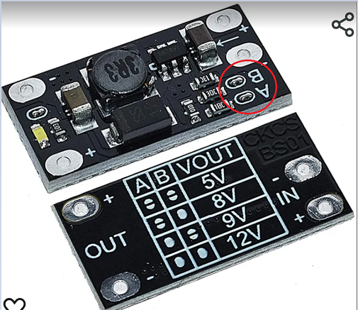
The default tiny zero ohm resistor jumper settings on the boards is for 12V, so for the 5 volt board, I just removed both of them. I looked carefully to ensure there was not a solder bridge. I alternately shorted them to ensure they they indeed changed the voltage. Only with both shorted did they provide the proper 12V output. All three other settings were higher than they were supposed to be.
While I was looking up this chart to verify that I did indeed have the jumpers correct, I noticed the error of my ways. This little board is designed for 3.7 volt input.
At some point I briefly looked at 3.7 volt batteries and I’m sure these converter boards ended up in my search history at that point. Later when I just wanted converter boards, I remembered them but I was too high up the ladder to see the the voltage 🙂
As luck would have it, 3.7 volts works fine for me, other than the expense of having purchased some 7.4 volt batteries that I don’t technically need, at least not for this part of the project. My charger will work for them, too.
However, I might choose better DC-DC boards.
I mentioned that these are inexpensive boards. $10 for a 10 pack. The voltage selection chart silkscreen on the actual board is completely illegible. All four setting for A & B look identically blotchy. And for what it’s worth, the output power pins are spaced 0.4″ apart, but the input power pins look at a glance like they are 0.2″ apart, but they are not. They fall somewhere between 0.2 and 0.3″. The output seems to be good for about 6 watts. The specs are somewhat iffy, but hints that higher voltages are probably at less than the 1A specified for 5V. The examples they give all work out to slightly more than 5 watts. This is fine for my needs. I don’t expect to need more than 150mA for 12V.
Until I put Activator board together, I’d been running this controller on either a laptop USB or a USB power pack. Now that I had it put on the board and running on my bench supply standing in for the 3.7 volt batteries that were enroute, it was nice to leave it on the kitchen table where it was close enough to hear the servo cycle, but but off my desk which was cluttered enough with the Trigger and ControlBox modules so that I could hit the buttons on them and observe the display on the ControlBox. For some reason, I had to interact with the Activator. I don’t remember why. While I was near it, I smelled that classic ‘something is hot’ smell. Since I had thrown over voltages at it earler, I finger probed and discovered that the inductor on the 5V board was pretty hot to the touch. I immediately shut off the power supply. I pulled to control board off, turned on the power supply and noted that the voltage was indeed 5 volts, so that’s good.
I presumed that the little 1A supply was having trouble keeping the controller and the servo both supplied, so I rewired the servo to run directly off the battery. That is a little below spec for it; it is rated for 4.8 to 8.4 volts, but in testing, it worked fine and still pulls plenty strong. I do not expect it to be a limitation for the Activator sear. Of course for the testing, the controller was plugged back in and in just a little bit, I smelled ‘hot’ again. I probed the power boards again and while it was not as hot, the 5 volt board was definitely getting warm. I probed around on the controller and ZOWIE a chip on the board was hot enough to immediately cause pain. I removed power again and pulled the board out. It turns out to be the USB serial chip. Once it cooled off, I plugged it into a USB cable on my laptop and it got seriously hot in a couple of seconds, so it definitely has a problem.
As mentioned earlier, I don’t think I connected the 7.4 volt battery to the system with the controller in place, thus applying basically 8 volts to its 5 volt input, but I can’t authoritatively say never. Plus, after working for weeks under various conditions, it acted up the day it was running on the new carrier board. The CPU seemed to be working, by the way. The USB chip was smokin’ hot, but even before I discovered it was baking, the device was responding to ESP-NOW messages and operating the servo. I’m just not sure it would have lasted much longer.
Happily, I have one not in current use, so I could swap it out. It is a slight pain to update the MAC addresses in the software to use the new device, but at least this one doesn’t sterilize the air around it. As these are my favorite boards for this application, small cheap boards with the external antenna connector and not a lot of unecessary IO, I may need to order a few more of them. I do have some 40 pin ESP32s with external antenna connectors, so I’m not without a way forward if needed.
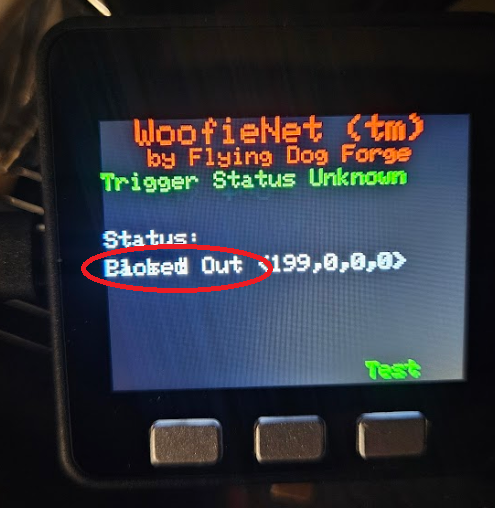
In other hardware news, I have been using a slick device with a built in screen for the ControlBox unit. I don’t know if this will be the final controller for the ControlBox, but it has it’s advantages.
It is an M5Stack Core. I originally got this for ESPHome use and HomeAssistant, only to find that it was not yet supported there. I have not rechecked lately. Anyway, it is an ESP32 in a nice case with a few built in goodies, most importantly for this, a 320×240 TFT display and three front mounted buttons. It also has a speaker, a TFCard slot and, while I’m not sure how long it can run on this, it has a 110mAh battery built in. I am thinking about building a little program to send a message to another module once a minute, with the other module logging the time and see how long it lives.
For use as a real ControlBox controller, it has one drawback. There is not a really strong way to secure external connections to it. It has a row of exposed pins on one side and exposed pin jacks on three sides. The pins are not ideal ones for reuse for my purposes and the pin jacks would be even more difficult to really secure the connectors to for a device that might get tripped over or dropped and has to travel on gravel roads in someone’s trunk or pickup bed. In the long run, I may need to use some descreet components for these setup.
But for now, it seems a good way to start, with a caveat.
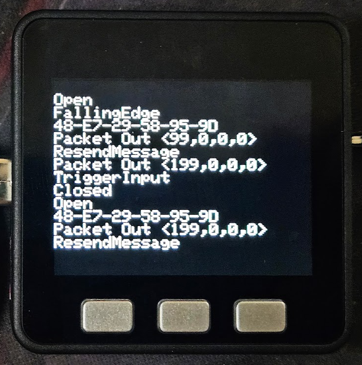
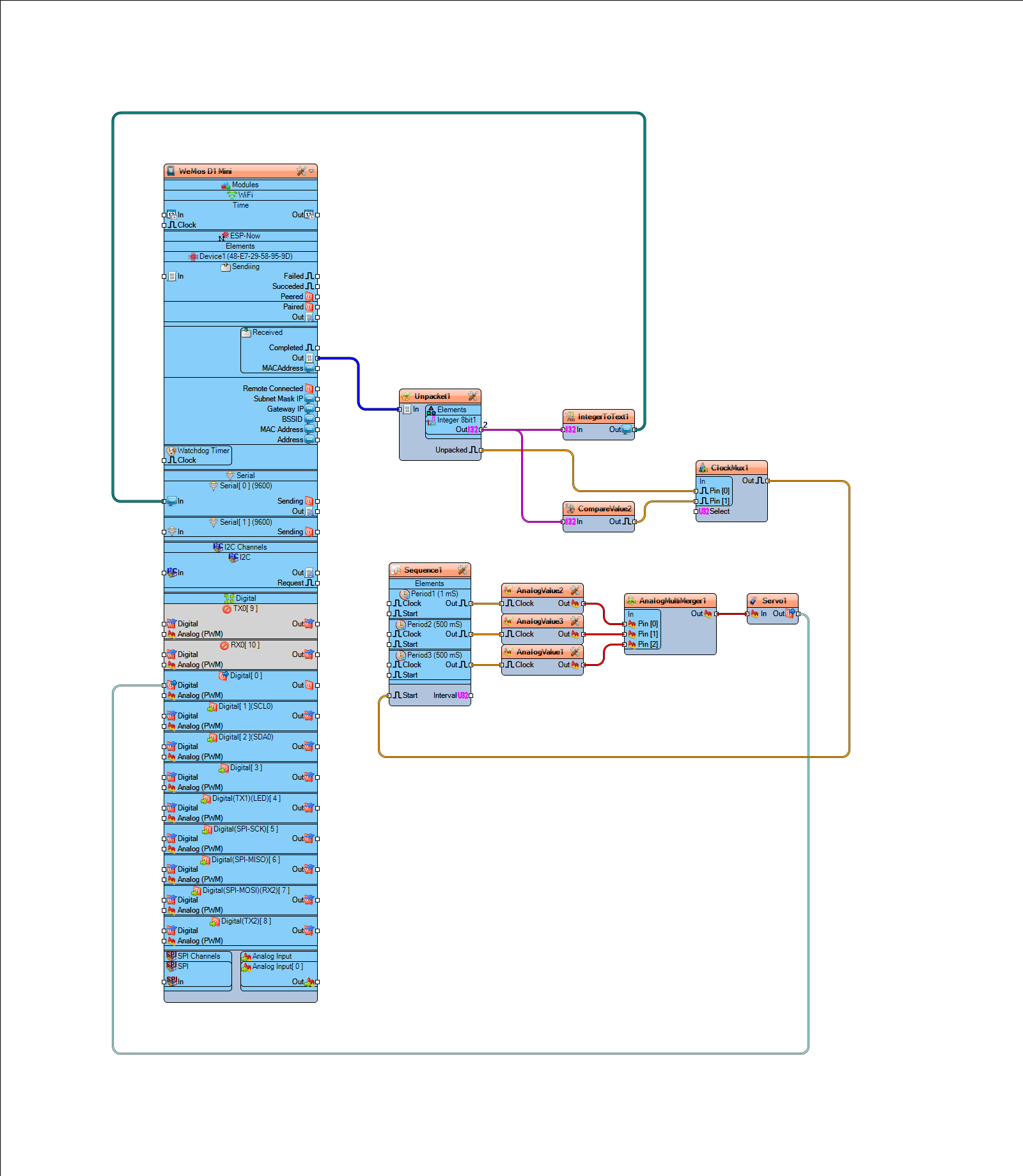
This was before I had it doing anything with text fields. I was sending stuff I would normally dump to Serial0 to the TFT instead.
I have found that, like many of these small hardware displays, or at least the libraries written for them, you often can’t just throw text at it and have it behave the way you would like it to, like scroll like a classic screen. On the screen as shown above, I can send one more line to it, then any subsequent lines will just continue to clobber that bottom line, text written on top of existing text.
Visuino supports text fields. The field is located anywhere on the screen by x-y pixel coordinates then prints text you provide with the font, size and color attributes your provide. But so far as I can find, there is no clear command. Subsequent text clobbers what’s already there. Argh.
I had been working on this issue reiteratively in what spare time I have for a few days now. I have a nice title bar and I intend to determine and display the status of the two (currently) available remote devices and provide a 3-4 line messages window of scrolling messages about whats going on, trigger received, trigger sent, test sent, device needs reset, etc. I have a label over one of buttons at the bottom of the screen and if you push that button, it sends a test trigger to the activator. All of these things work, until you put enough text somewhere to clobber what’s already there.
The only way I have found to clear the screen is to literally clear the entire screen, write it black, then rewrite all this stuff back to it. That seems completely ridiculous and it puts it on me to maintain a screen map somewhere. That’s not what I want to do. I want to make my hardware do stuff and print stuff on the screen to tell my users what my hardware is doing for them. The IDE should know how to make the *display* do stuff.
Sparse documentation is a recurring theme here. For example, these are two very similarly named components:
If you get context sensitive help for Delay, you get a Wiki page with thin but not entirely useless descriptions of the settings for the component and what the Start, Out and Reset pins do, as well as links to some example projects that happen use it.
Maybe Delay doesn’t do exactly what you are looking for. Logically, it seems like Timeout might do a similar kind of thing but attempt to get context sensitive help for Timeout and you just get:
It offers that you can search for it in other places, but so far, that has universally not helped on anything I have searched for. I suppose it could happen. Maybe I haven’t looked for the right thing yet.
Which brings me indirectly to my brief but severe irritation last night.
Regardless of this irritation with the documentation, I like the product. I was able to reach a working point with my devices very quickly. As always seems to be the case, a lot more time goes into the user interface than to the actual device (especially if you can’t figure out how it works). Anyway, I had been running on a 15 day trial version of Visuino Pro and there were two days left. I saw no reason to not proceed with the purchase. I looked at the version matrix and while I had been running the Pro on trial, I didn’t see anything in the Pro column that I was actually using, so I elected for the Standard version with a 1 year subscription for updates. The purchase, install and registration went through without a hitch. It automatically opened after installation and I pulled up the ControlBox project and played with it a bit. After a little while, I needed to open a second instance to make a companion change to the Trigger project. When did that, I noticed/remembered that I still had Visuino Pro installed and, fatally, decided to pull up control panel and remove it.
Long story short, had I removed Pro before installing the Standard version or reinstalled Standard after removing Pro, things would have been ok, but the removal of Pro removed all the components from the Visuino library folders. There was some minimal number of components that I guess are built in to the binaries and support for only the Arduino Uno R3, but my projects now spawned a huge list of errors, most of which were missing components and many of those were specific to my missing board. Once I had seethed down to being able to write without being overly abusive, I dashed off a note to Visuino support. I don’t remember exactly the details, but in short I wondered why the uninstall script would remove user files like all my components.
Interestingly, all of this was loaded on my work laptop, which heavily uses Microsoft OneDrive. Not long after my note to support was sent, OneDrive serendipitously popped up a dialog asking if I wanted to permanently delete the several thousand files I had deleted recently. I dove into that dialog and found that I could restore the folders that the Visuino uninstall script had deleted. I ran Visuino and everything was happy as it could be. I was was exhausted and shut everything down and went to bed!
By morning, I had a reply from Visuino support, patiently telling me that a reinstall would most likely fix it and that my own projects were safely stored elsewhere. I am certain that is true and I will probably do that because in restoring those folders, I am sure I now have some Visuino Pro components that I have technically not paid for. Then again, the program and/or license may be smart enough to prevent them from working. Shrug. As I noted when I looked through to version matrix, I wasn’t using any Pro components, which consisted mainly of FFTs and other such advanced data processing components. Interesting, but not applicable to anything I am likely to need for yanking on chains by novel means.
I have made what I think is a lot of good progress with both Visuino and the hardware.
The Visuino sketch shown in the last post kind of worked regardless of being very wrong in a couple of places 🙂
I had made a comment on a video about the recent massive expansion of Visuino. I noted how my code basically ran once when the first signal was received after power up, but since that same value gets sent repeatedly, the received message never changes and the code never seems to see subsequent received messages. None other than company founder Boian Mitov replied, asking for my program and details so he could offer suggestions. I excitedly sent a (far too wordy, as is my modus operandi) email and expectantly waited. Of course, I continued working on it and found a (naive) workaround that (kinda) worked, though it would come to light later that it was not actually responding to *the* command, but rather *any* command.
Several days later, the reply came from Mitov, with apologies for the delay, but with a beta update of the software that had several changes, including how the CompareValue component works. Between the guidance provided and my own experimentation in the mean time, I was definitely set upon the proper path and that piece of code was *truly* working!
My current design has three main devices, the Trigger, the Activator and the ControlBox between them. I have three ESP8266 devices, appropriately labeled Trigger, ControlBox and Activator. Trigger looks for a button press and upon detecting it, sends a message indicating that to its ESP-NOW peer, the ControlBox. At this point, ControlBox literally just retransmits the received message to its other peer, the Activator. Activator receives the message, verifies that the message matches the command to act and then cycles a servo, which will trigger the mechanical yanking device.
ControlBox will also have a dry contact input so that Trigger is not necessarily needed in all cases. Eventually, ControlBox will have a display and buttons driving a menu system where various behaviors and parameters can be selected.
At one glorious point, all three ESP8266 boards were scattered across my desk, communicating wirelessly at a range of 10’s of centimeters. It looks more chaotic than it really is.
The Trigger device is circled in green, the ControlBox in red and the Activator in blue.
As it currently works, pressing the button on the Trigger sends a message (an integer, 199) to the ControlBox. At this point, the control box retransmits the received message unmodified to the Activator. If the received integer at the Activator is 199, it cycles the servo, which will one day soon trigger the spring loaded device.
Future features will include a sense switch in the activator to warn people at the ControlBox that it has not yet been physically reset. Because of the way stages are reset between competitors, some triggering devices can inadvertently trigger a moving target before the stage reset is completed, so being able to arm/disarm the Activator from the ControlBox is a necessary feature. Since all these devices will be run on batteries, a battery status indication at the ControlBox will help ensure that all devices are ready to go. Finally, the ControlBox will be able to sequence multiple Activators. This is a rarely needed feature, but if my device can do this, it will sell 🙂
The fun bits that I have learned along the way:
I need to accomodate either a normally open or normally closed input for the Trigger. The DigitalDemux component makes that pretty simple. The contact goes to the input of the demux. The select switch goes to a DigitalToInteger component to provide a selection for the demux. The outputs of the demux go to EdgeDetector components, one configured for rising edge and one configured for falling edge. The same logic will be duplicated for the electrical input of the ControlBox.
When I first implemented the ControlBox, I over complicated it. Out of hardware hacking habit, I tried to use the minimum number of bits possible. I had set up the Packet and Unpacket components to use 8 bit integers. This worked, but somewhere in the mix, an integer is a 32 bit value and wrestling with resolving that was becoming troublesome. I had a situation wherein the first byte of the full integer was being interpreted as the command byte and that first byte was *not* 199. Eventually, I realized that ESP-NOW sends a packet with a minimum of 36 bytes and whether I send a payload of 1 byte or 4 bytes makes about 10% difference in the entire message and dealing with a regular signed integer is simpler than trying to shoehorn my ancient bitbanger ways into the mix. Once I abandoned all the conversion necessary for 8 bit integers and literally connected the received output to the transmitter input, it just worked.
The Activator has been the problem child and was the original reason I posted the comment on the YouTube video. It needs to react to an ESP-NOW command message, but only the right command. Other commands might include a status request, a command to turn a light on or off or a command that sets an operational parameter. I can’t just assume any message is a command to activate. This is why I was struggling so with the the old CompareValue component. However, the new version works better and other advice from Mitov cleaned up everything else. The chain is very simple and straight forward now. The received message is tested to see if it is the activate command. If so, the EdgeDetect component converts that to a clock pulse, which activates the sequencer to cycle the servo.
I learned that the sequence works slightly differently than expected. The Analog Value is set immediately, then the sequence time elapses. I first presumed that this timer was started and ran, then at the *end* of the sequence, the AnalogValue would be asserted. Now that I realize the proper order, then of course that makes more sense than what I was thinking. However, before I figured that out, there was a noticeable delay between when the button was pressed and when the servo moved. With copious serial prints I was able to verify that the delay was not in the transmission or reception of the ESP-NOW message; that is essentially instantaneous. The delay came from my misinterpretation of the Sequence component. Originally, I was setting the servo to 0 for 10mS, then for 500mS setting it to 90 degrees, the setting it back to 0 for 500mS. The intent was to first ensure that the servo was in it’s home position, then move to 90 degrees, with the first 500mS to ensure it had time to move, then move back to 0 degrees, again with a 500mS time to ensure this had time to happen.
Wellllll… turns out we don’t need most of that. The Servo component includes an initial value, which apparently homes the servo automatically at startup and then the timing of the sequences was not where I thought they were. The AnalogValue for moving the servo is asserted immediately, then 500mS later, the return to zero value is asserted. This is much simpler than I first presumed and makes for MUCH more elegant process.
If I were to make any complaint about Visuino, it would be that we need some kind of programming guide to demystify the inner workings of these components. The examples in the plethora of available videos often show what to do to make a light blink or whatever, but rarely describes *why* a certain feature is used. For example, a demo on operating a servo had a DivideByValue between the selected AnalogValue and the Servo. Only after extensive experimenting did I figure out that this provides the appropriate fraction needed to scale the degree value requested to the range of PWM that the particular servo will respond to. In the absence of more precise guidance, one could easily assume that the Servo component scaled these degrees itself and would accept a degree value as input. Quite accidentally, “0” and “90” as direct inputs to my servo appeared to work properly, but it turned out to be not 90 degrees, but the full 270 degree range, viewed I would say “backwards”. 0 went to zero, but “90” was so far beyond the 0 to 1 range that it simply went to 270 degrees. As it is a digital servo capable of 360 degree rotation, it took the shortest path counter-clockwise to the requested position, as opposed to the long way, 270 degrees clockwise. Some documentation revealing that the servo requires a 0-1 range instead of a direct degree heading might have revealed this issue much earlier in the process.
As for the hardware, I began laying out prototype circuit boards for the system, starting with the Activator. This is how it turned out before I started wiring it up.
At the top is the ESP8266 board. In the middle are two boost regulator boards (more on that in a minute), a cheap motor driver board that will actually be used to drive the warning light, with room to drive a motor in the future. Along the bottom are connections for the battery, external power switch, sense switch for the punger and the light and finally, the header for servo to trip the sear.
With the power supply boards, I got a little too clever for my own good. They were spec’d out when I was contemplating 3.7V batteries. I don’t recall why I landed on 3.7 to start with, but I did. These boards take a 3.7V input and boost it to 5, 8, 9 or 12 volts, configurable by removing the jumpers A or B or both.
Somewhere in there, I decided to order 7.4V batteries instead of 3.7V. Luckily, I decided to test the voltages before firing up the board because running with 7.4V batteries, the he lowest available voltage is about 8 volts. I have 3.7V batteries enroute.
In other hardware news, I acquired a rather nice carbide metal cutoff saw. This thing makes amazing essentially mirror smooth cuts!
This 2×4 14ga tubing was cut in 10-15 seconds and looks like this!
One can find plenty of derision online concerning the Arduino IDE. Shrug. Maybe I am not sophisticated enough to care that much about the occasional issue. I do have two main gripes about it. Once you start a compile, there does not appear to be a way to abort it. This comes up often for me because I will make some change that needs to be compiled and uploaded to test, then while the compiler is still building, I will see some other error that I need to correct. The best I can so is unplug the board so that at least the upload will fail. That brings up the other issue, although this may not be specifically an Arduino IDE issue so much as a general hardware issue. All of these devices that I am working with connect to the PC via USB. Sometimes, all the unplugging, replugging, pressing the reset button on the boards, etc, will cause the USB subsystem to kinda get lost. I don’t know if it’s the IDE, the UART chip drivers on the boards or what. Related to that, those UART chip drivers don’t always get along with USB 3.0. Since I do 99% of this work on a laptop that has two available USB jack, I use a USB hub that happens to have two USB 2.0 jacks and one USB 3.0. My current project requires me to develope on three interconnected devices at the same time and one of the available jacks on my laptop is occupied with my USB headset, it can be pretty easy to forget and plug something into the USB 3.0 jack on the hub. I realized this is a problem once the cards kind of stop responding. Thus far, it takes a reboot to restore trustworthy function.
So, besides all that, I find the Arduino IDE itself is just fine, at least until you have to communicate with something more complex, like a TFT display. The data being fed to the working display is generally not the issue; it’s getting the thing working in the first place. A problem that I had early on, though I have largely solved it by now, is that ESP-NOW is implemented a little differently in the supplied libraries for the ESP32 and the ESP8266. My intent was/is to put tiny ESP8266 boards in the remote devices and a more capable device equiped with a screen and some buttons driving a menu system as the controller. The example code provided for the ESP32 family is much closer to a good starting point for my project than the examples provided for the ESP8266.
The library names are slightly different, which is itself easy to fix, once you know the right library names to use. Trickier to solve, however, is that a very important data structure is slightly different and at least one constant name is different (ERR_OK vs ESP_OK). Luckily the incredibly helpful Programming Electronics Academy published a video on exactly this subject, using the example code from the ESP32 family and modifying it to run on an ESP8266, although I was not aware of it until I was a couple of days into trying to find and solve the problem myself.
Armed with this info and some time to figure out exactly what I needed to accomplish, I got two devices working and the devices can send and receive data from each other.
Next, the ControlBox device needed to be able to send it’s data only on demand. I replaced the delay loop with a few different implementations of detecting a button press. It’s roll as the ControlBox will require it to accept some kind of switch change to send that Activator the go command. Eventually, it will be able to respond to either a local switch or a remote ESP-NOW device sending the appropriate request.
With the button sorted out, I started the activator conversion. The current analog system, where we just throw voltage at a door lock motor to trip the activator. This fairly elegant and thus far very reliable. However, the lock motor is physically large and even though used only briefly, it is pretty power hungry as well, requiring an also physically large industrial timer relay to protect it. Converting this activation device to a servo will recover the space that will be better utilized by a battery in the new design and the servo will arguably require less power.
Getting a connected servo doing *something* itself fairly easy, but getting it to do precisely what I want it to is much more difficult.
As I never stop putting “ESP NOW” in the YouTube search, I stumbled across another way to do this stuff.
The video that introduced me to Visuino makes no mention of it in the title, but as I watched it, there was this visual IDE being used. It was almost mentioned in passing, but in very nearly 8 or 9 minutes real time, an ESP32 board and an ESP8266 board were set up by dragging virtual components onto the screen, interconnecting them with on-screen wires and a few settings in the components. One has a temperature/humidity sensor and the other a small OLED display. The display on one shows the temperature and humity data from the sensor on the other.
It is pretty easy to argue against using such packages from a strictly code efficiency point of view. Visuino produces code that is essentially impossible for the inexperienced programmer to follow and the code sizes produced would not be unfairly called monstrous. My most complex sketch to date (spoliler: I am using Visuino) is nearly 300K and doesn’t only slightly more than the 3K Arduino IDE code that preceded it. These ESP controllers have megabytes of RAM and FLASH to work with, so it is kind of a non-issue.
All is not perfectly rosey, but with an hour or so of judicious tinkering, I had a working receiver, receiving the data sent by my “old” Arduino code. Getting it to activate the servo based on receiving that data turned out to be tougher to figure out, though largely becase I struggled with the kind of object oriented approach after so much time in procedural methods.
The the knowledge gained by the receiver project, it was much easier to reconfigure the sender into Visuino and then to add a button to the sender.
Just this morning, I succeeded with the quick and dirty version of what will one day be deployed in the field, a Trigger device that will initiate the action, a ControlBox to intervene and/or modify before it sends the command on to the Activator.
The Trigger (green arrow) responds to a switch closure and sends a byte of data to the ControlBox (blue arrow) which resends it to the Activator (red arrow) which does a quick 90 degree cycle of the servo (yellow arrow).
For this quick demo, I am using all ESP8266 boards, specifically the Wemos D1 Mini Pro, which supplied with an external antenna connector. Since at least one of these devices will be inside a closed steel box, the external antenna is likely to be a requirement.
The 8266 boards are perfectly appropriate for the two far ends of the system and probably fine for the ControlBox as well, however I would like to put something with a screen and menu buttons on the ControlBox so that features can be selected in a friendly way. The list of features are still a work in progress list, but includes things such as being able to detect and add new devices and the ability to trigger multiple activators, maybe with a timing sequence between them. There quite a few controllers available that already have a screen and buttons and other features ready to go, taking away some of that development time required to make the interconnections between those peripherals and Visuino makes using those peripherals easier. Maybe.
One problem I face with Visuino is that, while there are a lot a supported devices, I already have several devices that would be appropriate to try, but they are not implicitely supported in Visuino. The Arduino IDE provides a pretty easy way to add support for new boards by providing a list of URLs where the supporting device descriptions can be pretty much transparently downloaded. There is a similar list viewable in Visuino, but thus far, I have not found a way to add to it.
Ok, maybe not stupid, but I did miss something pretty fundamental and I missed it early enough to waste a couple of days of development time. Also, there was a side quest through the quicksand that is Windows USB drivers.
As mentioned earlier, ESP-NOW is expected to fulfill a number of needs for my project. To recap, I have built a reliable target activating system applicable to several shooting sports I am involved in. It is reliable because it is electrically pretty simple, with some switches and relay providing the limited logic needed, a control box with said relays and switches and a battery and finally the connectors and cabling to hook it all up.
Removing those cables can be done with a wireless system that essentially doubles the built cost for the system. It would also be plenty reliable, but the cost is prohibitive, especially as I do intend to sell this system and I can’t make the price attractive and make a little money on it if I have to spend that much on the wireless technology.
The hardware for ESP-NOW is built in to microcontrollers that already support WiFi and are incredibly cheap. Furthermore, adding a microcontroller will let me replace a couple of other expensive parts while added even more features.
Of course, ya gotta get it working first.
I had easily set up two devices where one could messages to the other. I found an easy to follow YouTube tutorial for two way communication between two devices and chose that one to implement for the next step. The tutorial had a lot of symetry to it. Two ESP32 devices, each with an environmental sensor (temperature, humidity and pressure) and a tiny OLED display. The environmental data from each device was displayed on the other. The sketches are identical on both devices other than the manual entry of each devices peer MAC address, the device it is sending data to. While some of the ESP-NOW tutorials included facilities to scan for peers and automatically record their MAC addresses, this one assumes you know the MAC address for each of your devices and even includes a super simple sketch to extract the mac of the board it runs on. I ran this sketch and recorded these MAC addresses in a notepad text file for later reference. The sketch requires the MAC address to be stored in an array variable and in the declarations area of the sketch, this array variable was created in this form…
… where you would substitute the MAC address octets of the peer device for 0xFF in each position. If you leave it all FF’s, it will work by broadcasting the data to all devices on the network and the ESP-NOW devices will actually listen. However, the receiving devices do not acknowledge receipt of the message, where as unicasting to a specific MAC address does. There are situations where broadcast is appropriate, but for my purposes, I’d rather have the acknowledgement.
In my notepad, I created this string of hex notation digits so that I could just copy and paste the MAC into any script I was working on.
I modified the sketch, simplified it, removing all the code to support the display and environmental sensor because I didn’t have those to connect to it. My sketch sent two bytes to each other. Eventually, my messages between units will also be just two bytes, on as a unit identifier, the other as a command or status. I could probably make that two nybbles and just send a single byte.
The trouble is that my devices would only send one way. I had intended one to be the Activator and one to be the Control Box. Under normal circumstances, the Control Box will send a command to the Activator to instruct it to trip immediately. The Activator will either periodically send a status or it will respond to a poll for status from the Control Box. In my case, however, communication was also only one direction. The sending unit did not have an acknowledgement and the receiving unit never received any messages. I did a few minor troubleshooting steps to ensure that my sketches were indeed identical other than the peer MAC addresses.
The next step was to swap out equipment. I was using one ESP32 for the Control Box, assuming I would want to add more features to that one eventually and they have more I/O pins. The Activator was a very inexpensive ESP8266 board and there was always a chance one might have a bad transmitter. When I started swapping boards and sketches around, the laptop would occasionally not drop the virtual comm port when a board was unplugged. It would sometimes take a reboot to clear this issue. I had two instances of the Arduino IDE running. Juggling two IDEs and two of about four available cards when sometimes the USB subsystem would basically stop responding and require a reboot to fix quickly grew tedious as hell. I reached a stopping point on the first day and had to drop it at least overnight.
The next day, I decided that, since I was fighting some weird issues, I would work with some ESP32 boards instead of the 8266’s. The libraries for ESP-NOW and WiFi are different between the two MCUs. It was just a variable wanted to eliminate. The situation was largely unchanged, including the USB virtual comm port issues. I had a new sympton there. Now sometimes, I could get two of the same virtual comm port number. A bit of research revealed that sometimes, the USB to serial chips on these boards will have the same serial number, at least as far as Windows Device Manager can tell, so it give them the same comm port. I could manually edit one of them to an unused port number and make them work, but the more I unplugged boards, the more often the entire subsystem would lock up. Reboots would take several minutes, then time out with an error “DRIVER POWER STATE FAILURE” and it would then reboot itself from the reboot process. It happened several times and took 5-10 minutes EACH TIME to complete a reboot. That was the clue I finally latched onto and worked on replacing the driver for the USB to serial chip on these boards, the Silicon Labs C210X series.
That is an easy download, but of course by now, things weren’t going to go easy. Eventually, I discovered that there were three separate sets of Silicon Labs drivers installed on my laptop. I presume there was some subtle difference between some of the ESP boards I have plugged into this laptop and each installed it’s own ‘most recent’ drivers. I deleted them all and installed the fresh download from Silicon Labs, dated in 2023. This seemed to settle down the USB traumas.
Of course, they would still only communicate in one direction.
Now that I felt like I could trust the USB stuff, I added some code to print the device’s MAC address and peer MAC address during the setup() function. It never printed. I added other tag prints to show where in setup execution was. Those never printed. It was like it was skipping the setup() function. Google again.
Eventually, I found some references to the serial port/driver being slow to come up at boot timer or after an upload. One solution was to use a while loop to wait until the serial system was active. That didn’t help, either. Finally, one suggestion was to literally wait for 5 seconds before executing the Serial.begin() function and that finally worked! It was kludgy and needed only for sanity checking while developing, but it worked. The two MAC addresses printed out.
Since I copied and pasted the information into my notepad file, I have no idea how one of those MAC addresses was wrong and more importantly, how a C got changed to a D. They are adjacent keys, but good grief.
It can easily be argued that fixing the USB driver thing definitely needed to be done, but because of that distraction and the slow start on the USB serial port connected to it, troubleshooting a friggin’ TYPO took two days.
In my last post, I went over some mile high view details of ESP-NOW and my plan to replace the largely analog control scheme for my target activator system with some microcontroller boards running ESP32 and ESP8266 chips. That these systems can provide wireless communications for far less than the cheapest alternative that I had found thus far. However, in making that jump, there are many other advantages, some of which feed from one another, but all rooting in using the MCU boards to control the system.
The control box primarily becomes just more control-y, able to leverage MCU features in the activator and trigger devices. The control box will have user friendly lights to indicate whether the activator has been reset and the trigger is ready. With an arming feature, it will be able to ignore trigger inputs during stage reset. With wireless triggers, there is no need to choose an input polarity. Once a later version is configured with a display, more sophisticated features, such as sequencing multiple activators from one trigger or battery charge level from remote devices.
The activator benefits in several ways, where using an MCU introduces cascading improvements. Immediately, I realized that a big problem will be that the activator will now need an internal battery. Since the MCU can take over the timer relay’s one function, that relay can come out, leaving more room for the MCU and a battery. I don’t need a connector for the wire, but I will need a power switch and the external antenna.
I was watching a YouTube video about multitasking MCUs. One of my favorite videos on the subject involved adding more things that were happening at the same time, first a blinking LED, then an LED that fades in, then a button that lights and LED and finally a servo that sweeps, with all of these running simultaneously. BTW, all of that revolves around programming the various delays needed without using the built in delay() function because the MCU can do nothing else while that particular delay is running.
Wait a second, ‘servo’? Epiphany! I can replace the 12 volt lock motor with a suitably strong servo; I don’t need to protect the lock motor if there is no lock motor to protect. Oh, and any servo will be a LOT smaller than the lock motor, so now I have more room for the battery. Oh, and the lock motor was the only reason I was going to need a 12 volt battery, so now I can use a smaller battery, like a 7.4 volt RC car battery, which are made to be easy to swap out and charge.
Hardly mentioned thus far is that the trigger devices can be remote and wireless. There is a good argument for keeping the hardwired connector for certain triggers that don’t really need to be automated. On the other hand, a wireless trigger appliance that hardwired triggers can plug into makes all triggers look alike to the controller software.
The short version (I know, I’m not good at telling the short version of anything) of implementing ESP-NOW is that there are quite a few serviceable example sketches showing how to set it up and get it working between almost any number of devices. The examples tend to show unidirectional commuications, with one or more transmitting devices paired with one or more receiving devices. At minimum in my application, I need for the control box to receive from a trigger device and send to an activator device. The control box really needs to be able to communicate in either direction. Taken a bit farther, an activator needs to be able to send it’s status and a trigger might need to be able to receive a command, so from the ground, I need to deploy them as bidirectional.
At this point, however, I am pretty happy to have unidirectional communications that is responsive. In the little video below, the window on the left is the ESP32-S3-Box set up a the sender. I have a button push set up to trigger it sending it’s data, in this case the number ’25’. On the right is the D1 Mini Pro set up to print any data it receives as soon as it receives it.
This video is not particularly easy to see the details, but I think you can tell that there is only a tiny delay between when the S3-Box senses the button and when the D1 Mini displays the received data.
Interestingly, the button press needs work. No matter how debounced the button is, it somehow sends the data twice per button closure and once upon button release. None of the logic in place *should* do that, but it does. I suspect it will be because the example code scans for all slave devices and puts them in an array. The button press triggers a loop which counts through the list of slaves and sends the data to each. I am guessing that something in that loop is to blame for the multiple sends. I don’t want to completely eliminate the loop because a near future version needs to e able to sequence through several activtors. Plus, my button press might not be perfectly well executed. Maybe it isn’t as debounced as it should be.
My first implementation of the wireless setup will actually have the units hard coded to eliminate such issues until I am ready to tackle them. I don’t need to be fighting on multiple fronts.
The activator software really doesn’t need to do much for a successful version 1.0. Receive the activate command, operate the servo as required to release the physical device, then sense whether the physical device has been reset or not.
Once I had really decided to go with the MCU route, the primary trigger device that I have been thinking about is a ESP-NOW equipped photobeam sensor. Like the activator, version 1.0 of the trigger doesn’t need to do just a gob of stuff, just send a signal to the controller when triggered. Everything after that is gravy.
There is one potential problem. The photobeam I *have* requires 12 volts and all the alternatives that work in the same basic way, with the emitter and detector in one device that points to a retroreflector on the other side of the detection area, also all start at 12 volts. This means that the trigger device will either have to have a different battery than the control box and activator, or I need to get 12 volts from somewhere.
There are boost voltage converters that use switching power supply technology to boost voltage. Of course, there is no free lunch, so a boost converter draws the same amount of power it converts. To supply 12V at 1A would take 1.6A from a 7.4V battery, plus a little to account for efficiency loss. Happily, the photobeam draws 40mA or less and, at this point, I’m not sure how much the D1 Mini Pro pulls, but I’d bet I can probably use one and a 7.4V battery and be just fine. I guess we will find out.
Longer term the the data protocol I develop should include the activator and trigger devices sending a periodical status packet. This will be used as a general keep alive communication, but the structure of status message will include a device ID that the user assigns, a bit or two to identify that type of device it is and other status information, like battery condition and whether the activator needs to be reset. I have 250 bytes to play with, but one or two bytes should suffice.