As expected, using an internal fuel pump externally presented a little issue.

As can be seen (blurrily, sorry) here, there is an inlet at that would be the bottom of the pump. This inlet was originally connected to a screen and surrounded by what was basically steel wool, forming a simple fuel cell. I connected and clamped a length of 3/8″ fuel line with an inline filter to this inlet. It’s not a very long nipple, so I expected to need some way to stabilize the connection for installation, but for bench testing, this was ok. I connected the outlet to the regulator with 5/16″ fuel injection line and the relief port of the regulator to a length of 1/4″ line. The free ends of the 3/8″ and 1/4″ were plunked in a gas can. The plan was, apply power and if it works, it will build pressure, trip the regulator and all the relief will flow back into the can in a closed circuit. It took a bit of priming to get it lifting fuel out of the can, which won’t be an issue on the bike, and looking only at the two ends, the fuel flowed as expected!
All was not rosy, however… in this view, you can see a smaller hole, in the upper righthand area of the endpiece. This hole spews gasoline under pressure when the pump is running. In the in-tank installation, this would have simply flowed back into the sump in the tank where the pump was suspended. I suspect that it’s part of the cooling scheme for the pump motor.
I analyzed the circuit and I have decided that there is probably adequate flow through the pump and regulator and back to the tank to cool the pump internally, or at least I’m willing to try it. With the pump not submerged in fuel as well, it may well run warm. Gotta get it hooked up first to see….
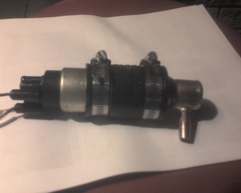
I elected to raid the plumbing shelves again. I found a 1-1/2″ to 3/4″ copper reducer that fit nicely to the end of the pump. I drilled a hole in the side of the 3/4″ end and fitted a couple inches of 3/8″ tubing there and brazed it in place. To keep the overall length down, I avoided using a short length of pipe and a cap to plug the end and instead cut a flat disk of copper from another fitting and brazed it to the 3/4″ end. I also cut the larger diameter end shorter. The adapter fits pretty close to the pump intake. The assembly is attached to the pump with a neoprene sleeve and hose clamps, originally intended to joining cast iron sewer pipe ![]()
Tonight, I hope to connect the whole thing and let it circulate for a while, checking the temperature of the pump and perhaps of the fuel as well. I want to pick up a fuel pressure gauge, but they tend to be either too large, too low pressure range or both. Guess I’ll have to order one…