The fuel pump arrived today, a $20 unit off eBay. The fuel pressure regulator also arrived separately.
This evening, I pulled the old pump back out and discovered, as I suspected when I opened the package, that the new pump is slightly smaller. As you may recall, a neoprene sleeve joins the body of the pump with an adapter I built. This adapter allows the pump, originally designed to reside submerged in the tank to instead be fed from a fuel line.
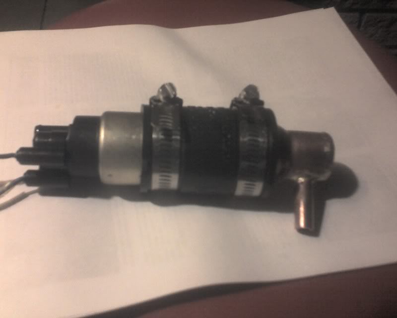
Well, the new pump, which I neglected to photograph (you can’t get good help these days), is enough shorter that there is only a small fraction of an inch of actual pump showing beyond the adapter. Also, the body of the pump is smaller in diameter, but not so much that the neoprene and hose clamp couldn’t seal it. I soldered pins on the wires and put them in a connector, plugged it in and verified that it would run dry. It was quite noisy, which surprised and concerned me at the time.
The new regulator is bigger than I’d hoped, but not as big as I’d feared. I took the adequate but busy stock gauge off and substituted my spiffy oil filled one. As for mounting, the size of the regulator would not turn out to be the problem.
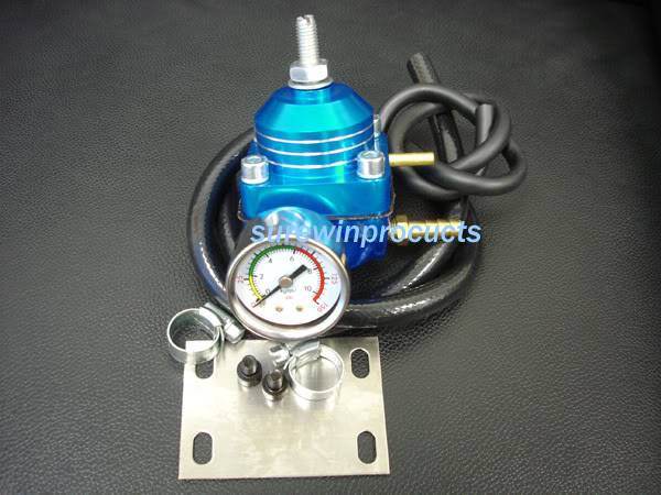
The regulator has a straight hose barb for input from the pump in what I’m going to arbitrarily call the ‘back’. In the front is the fuel pressure gauge. Sticking out from the lower right is another straight hose barb for the fuel return. Above that is a vacuum fitting (used to modulate the pressure according to vacuum; I will experiment with this, but for now, I have it capped) and finally on the top is the pressure adjuster screw. In short, the unit is roughly cubical in shape, but in operation, you need access to four of the cube’s six sides. I saw no point is orienting the device where the gauge could not be seen, so it pretty much had to mount with the gauge facing outward. After LOTS of trying and tweaking and test fitting, I finally decided to put it at an angle with the return fitting facing at about a 45 degree angle. The gauge is in almost the same position as before. The assembly is nestled between the air filters for 1 & 2, forcing the bottom edges of each to rotate out slightly. Filter #1 is almost vertical but #2 is angled more. Filter #2 isn’t normally visible, so I can tolerate it. Even with all this difficulty, the fuel system plumbing is simplified, largely because the pressure gauge fits on the regulator itself. Upon reflection, I can replumb the system with the regulator placed for better access to the adjuster and with the fuel pressure gauge remotely mounting where I can see it while riding. I have some ideas about that, too.
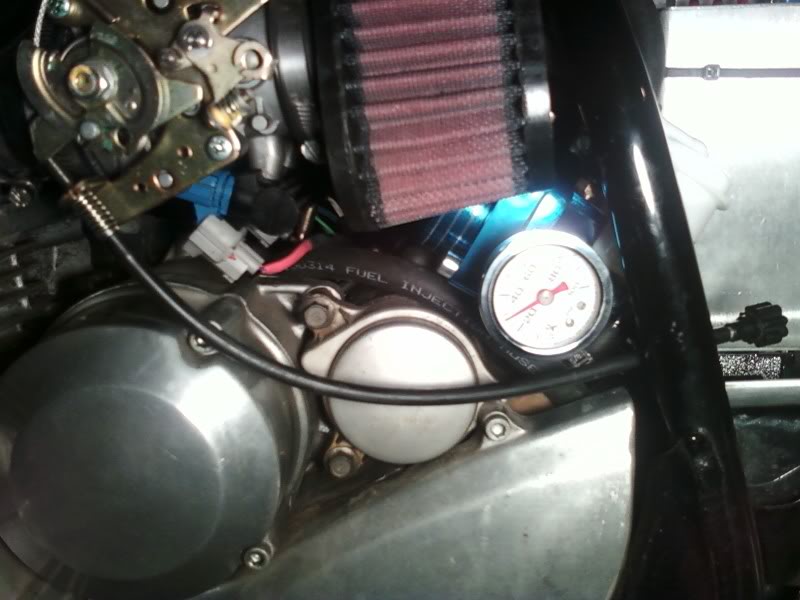
The engine is not running in this picture, but the system holds pressure well, indicating about 30 here. I have the regulator set to 38 psi, down from the fixed regulator’s 45ish. I had to reroute the return line, which involved accidentally pulling the line off the tank, which started it pouring. Argh. The clamp is on there much better now.
Then I had trouble getting fuel to start flowing. I think the filter element was wet (with fuel), so gravity couldn’t produce enough pressure to push the air in the line through the filter. I used the trust old siphon bulb and got it flowing. Once some fuel was flowing through the pump, the noise went away and now it sounds like it should, a tiny little whine. Likewise, the regulator has a quiet little honk while running with fuel, but when I used the air compressor to verify the the input and return, it sounded like an air impact wrench.
After all that, I finally was able to hit the starter button and Buzz leapt to life! While he was warming up, I unloaded all the tools from nooks and crannies and put the seat on. I took him down the street, around the block. I didn’t have to push him home, not even once.
I think he runs a little better on the lower fuel pressure. It’s hard to tell because the previous ride was so useless. In any case, Buzz runs at least as well has he did before the conversion, which is good, but not great. Good power on acceleration, but it could be quicker. It felt like I was rolling the throttle on, when in fact, I’d nailed it. In other words, rather than Vrooomm, it was more like Vrrrrrrroooooomm…
After circling the block and a little farther for several laps, I actually managed to get about 4 miles on the odometer. I then went to the gas station and filled the tank with 93 octane and endeavored to ride more. I spent more time on long straight streets with minimal stops. At the time, I was not brave enough to hit a freeway. I will try that in the warm daylight, just in case. In all, I clocked about 12 miles with no troubles.
At speed and very low throttle openings, it runs pretty rough. I’m pretty sure this is because at low consumption levels, the granularity between enough fuel and too much fuel is pretty narrow. At higher throttle openings, he seems to run really well.
All in all, a good day!