If your ecu box develops a water ingress situation (was a concern of mine when I had a location adjacent to the rear wheel before), an idea I added to my front mount alternator was a small, remote located computer fan (they run 12vdc) feeding a 1″ ID hose that develops very slight but positive pressure into a cover fiting over its front. This works really well in keeping it cool, as well no rain or spray gets into the workings, even tho its right behind the front wheel.Lorne
Monthly Archives: May 2010
On System Redesign….
Happens twice or three times a night sometimes… ![]()
I do try to think things through far enough ahead to avoid starting work on major segments before I have a decent plan. Reality almost always intercedes, however, and system redesign is the result. I prefer to think of it as refinement.
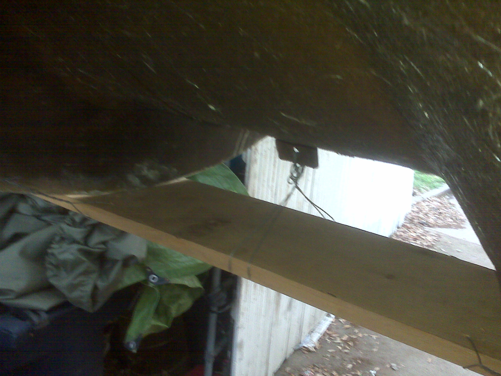
Recent work on the trike has been engine wiring, which meant choosing a place to put the ECU, which is not actually designed to be outside the passenger compartment of a car. I have placed the ECU in a sealed box, then proceeded to drill a big hole in the lid for wires.
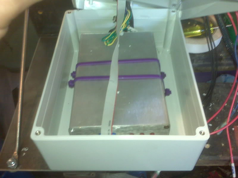
But, I think it will be well protected because I put a plate for mounting various electrics in a place that is centrally located under the fiberglass body, above the transaxle. The ECU is mounted to the “bottom” of the sealed box, but the box is suspended upside down on the bottom of the mounting plate (though it is not yet secured in the linked picture). This puts the hole for the wiring at the lowest point of the box and the ECU is inside the box at the highest point. Combined with sealant around the wire bundle, incidental spray should not be able to enter the box. The biggest compromise to this location is that it is immediately in front of the cooling fan intake. At highway speeds in the rain, it’s actually fairly likely that spray will be drawn to this area. No other mounting location is otherwise as desirable, so I hope that I have addressed all the problems.
You will note in that picture that I have mounted two fuse blocks. The one on the left is for engine and EFI stuff, the one on the right will be for chassis stuff, mostly lighting and instrumentation.
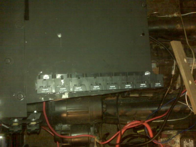
The row of relay sockets shown will be shortened somewhat. The forwardmost socket will interfere with the body. At this writing, only two of the sockets are in use, one for the main engine power and one for the fuel pump and O2 sensor power, as recommended in the wiring diagram in the MegaManual. The rest of the relays are mostly to allow me to use small gauge wiring to the handlebar switch pod.
I have also layed out the location for the EDIS stuff. Note the mockup of the plug wires. There is a tiny bit of concern about having the coil pack physically near the ECU, but I’m willing to try it. The alternative locations for the coilpack all involve building some kind of bracket for it and/or dodging some moving part or hot air flow.
Re: 70-something Stires Trike
I wrote: After that, it’s just wiring. A lot of wiring, but just wiring.
When is wiring just wiring? I thought I had my wiring in pretty good trim, but after a season of tuning efforts, and hind sight, I put the project back into my surgery zone (in house, basement workshop) and totally rewired and relocated key items like Micro Squirt, relay board, etc. Seemed like things kept changing as I discovered what was working and what didn’t, that ended up requiring a total rethink on the original plan
I look on that as normal and fun, family tends to see it as compulsive MS disorder behaviour (CMSDB if you will)
Good luck on yours.
Lorne
Getting Ready for Upholstery
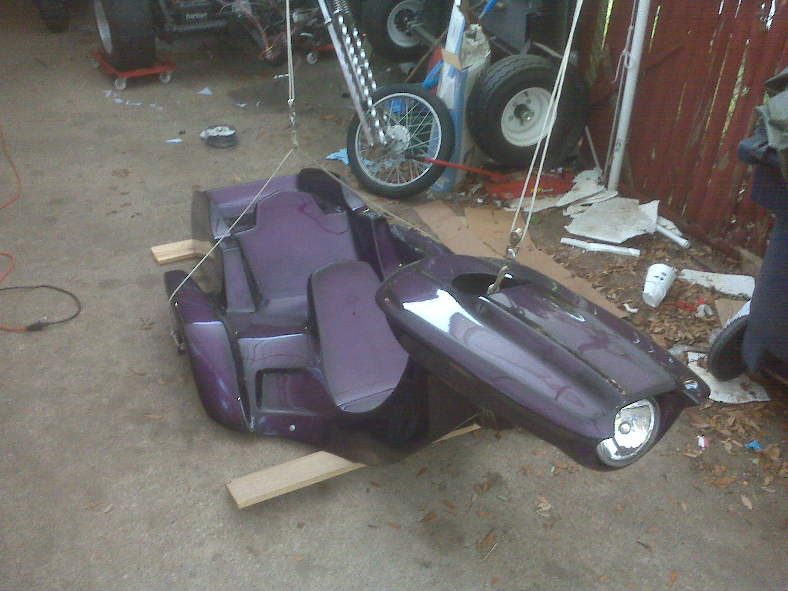
The first thing I did tonight was get the body ready for transport to Chris’ Trim Shop for upholstery tomorrow. I go get my material and drop both off for the work.
To protect the four “corners” that generally hit the ground first on the body, I wired and bungied a couple of boards to the low points.
The front still sat a little low, so I added a spacer to the bottom of that board, not shown here.
The board in the back is held on with a couple of ball cords laced through the tail light holes.
Now the body will be easier to handle with somewhat less fear of scraping the gorgeous paint job.
As for the upholstery, it’s pretty much a tossup between the left and middle choices. Since it’s only a couple yards of either, the fact that they are also the most expensive two is kind of incidental, $14.50 and $23.25 per yard, respectively.
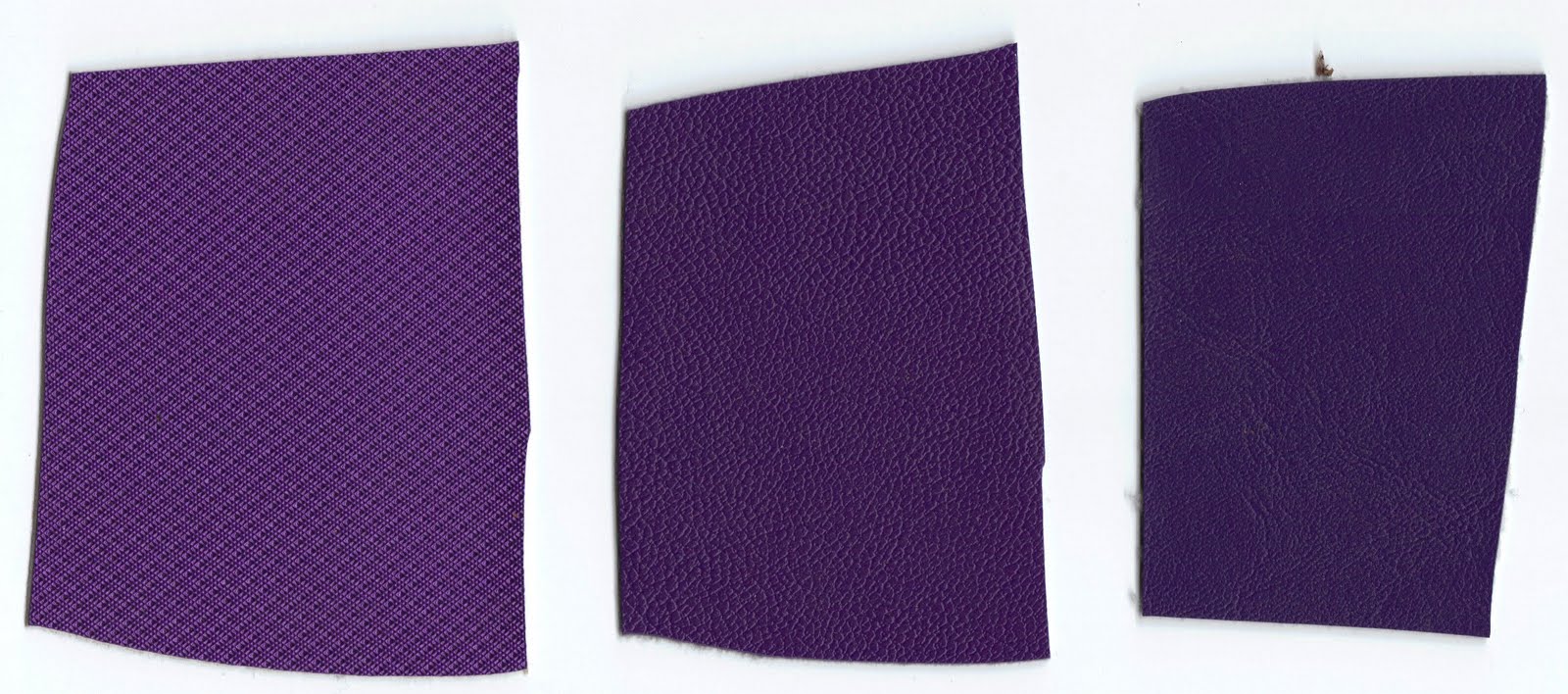
It seems to me that the left one picks up the brighter tones of the paint better and it appears to me to be the heavier of the two, so it may well win.
The other option, available from the trim shop directly, is a black covering that has a snake or lizard skin texture, which I think is pretty cool for a dragon themed trike. I found something similar in purple on the internet, but it was so cheap per yard, I figured it probably not good enough quality.
So, unless something really cool jumps out at me, it will probably the the left one above.
Malaria, Anyone?
Before the swarm of Asian Tiger Mosquitos chased me in the house, I got several more important bits done, leaving plenty to do tomorrow during the day while the vampiric minions from the East are busy dying from the Yard Guard.
While I will also be dropping the body off for upholstery, I intend to try to get enough done to attempt crank the engine. Admitedly, that’s pretty ambitious, butcha gotta have goals…
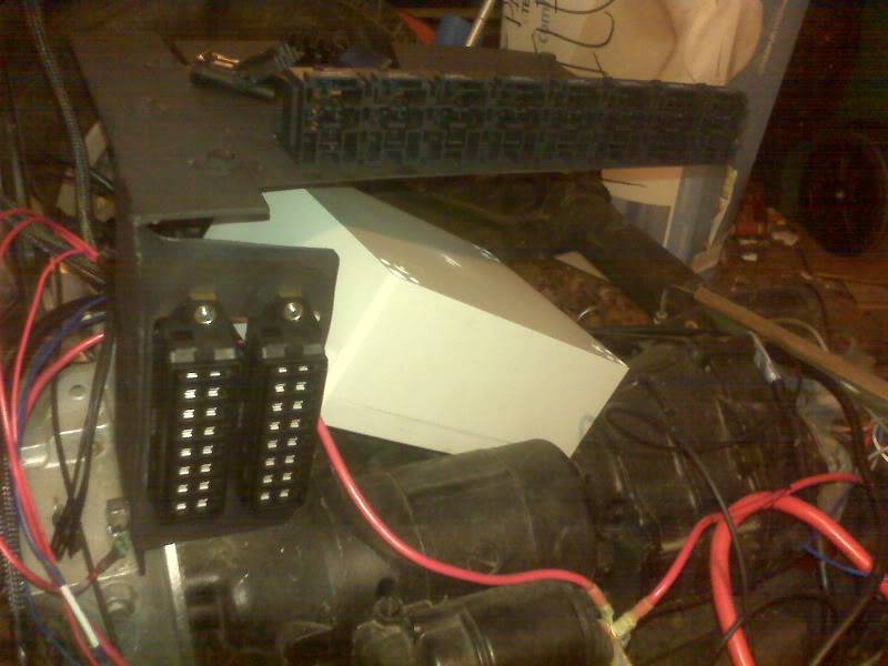
Mechanically, the biggest thing will be finishing off the fuel tank, which is putting the pump in it, putting the filler on top and mounting it. I also need to cut and mount the plate that all the relays and such will be mounting to.
After that, it’s just wiring. A lot of wiring, but just wiring.
The throttle body has connectors for the TPS and IAT sensors, as well as the IAC motor and two injectors.
Speaking of injectors, I still have not been able to identify the EX650 specific injectors well enough to discover their flow rates, so I substituted two injectors from the throttle bodies I removed from Buzz. Their flow rate is known to be 245 cc/min. Guessing at a couple other values and plugging them into the Req_Fuel calculator, these injectors should provide a reasonably long idle pulsewidth. This was a big issue with Buzz, where a 538cc engine was trying to idle when supplied with fuel from four of these injectors. This 1600cc engine with only two of them should be a better match. The nose of the 245cc injectors is slightly shorter that the stock ones, but I don’t expect it to be a problem.
But back to the wiring…
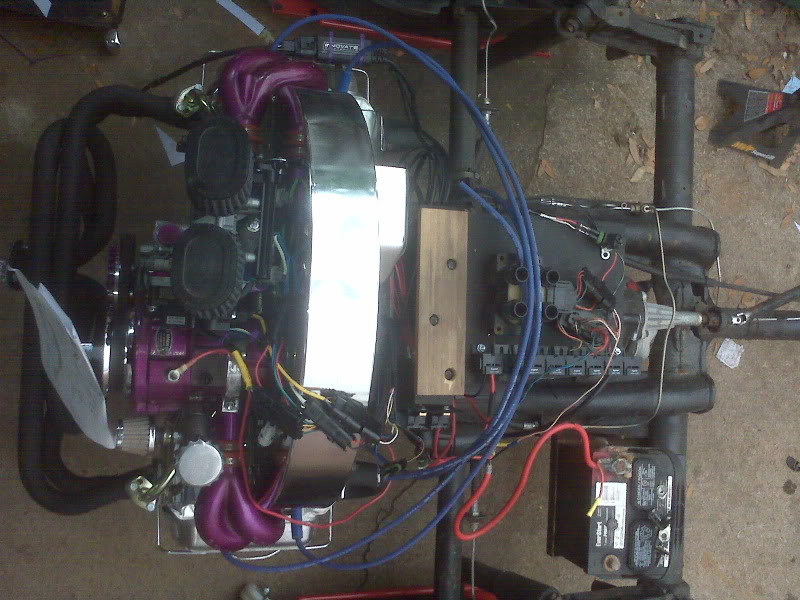
I have a waterproof box to put the ECU in. Hopefully it won’t run hot in there. All the relays and fuses will be on a plate or board just in front of the engine.
Re: 70-something Stires Trike
R100RT wrote:Very nice work, and project coverage.
Thanks! Having seen your own project documentation, I consider that high praise. ![]() I have browsed a LOT of these stories. I try to emulate the ones I have learned the most from, thus I tend to explain as much as I can, even when I screw up. It may help someone else. Heck, I might need to refer back to it to see what the heck I was thinking when I did *that*…
I have browsed a LOT of these stories. I try to emulate the ones I have learned the most from, thus I tend to explain as much as I can, even when I screw up. It may help someone else. Heck, I might need to refer back to it to see what the heck I was thinking when I did *that*…
Plus, I like to write almost as much as I like to talk.
R100RT wrote:Will your front wheel (I assume that’s the one you’re showing?) have disc brakes on it?
The front wheel is from a Honda Passport. I will be using the stock drum brakes. On a VW trike, especially one with a small front wheel, the front brake is little more than a handy way to keep the trike from rolling around at a red light. Between the light weight on the front and the relatively small bit of contact patch with the pavement, the front brake does not contribute significantly to the overall braking performance. It is easily overwhelmed by the relative bulk of the rest of the vehicle.
The old wheel has a really badly rusted section on the rim, so I wanted to replace the wheel for safety reasons. Since the “new” wheel has a functional brake, I have decided to use it. Besides, there is some question as to whether or not a trike with no front brake is actually legal in Texas. There are plenty of them out there, but there is conflicting information about it in the Texas Transportation Code. One bit says that rear brakes are all that is needed if they meet braking performance standards, which are fairly clearly defined. However, another bit says that brakes are required on all wheels of motorcycles, and since trikes in Texas are registered as motorcycles, many inspectors require brakes on all wheels.
R100RT wrote:…I’m considering stripping everying, and going with powder coating.
I personally like the look and feel of powder coating. I am very lucky that a friend works in a facility that powder coats some of their own products. So long as the color limitations (black, gray or baby poop brown) is not a problem and I’m willing to wait an undetermined amount of time for them to get around to it, I can generally get almost anything powder coated in exchange for beer. Since black is the only real choice with that, I decided that paint would be better for the wheel. Hopefully, I wont destroy the finish lacing the wheel.
Going in to turn four
I have basically 21 calendar days until Memorial Day Weekend, which is when I want to unveil The Dragon Trike, and only two more weeks after that before Trike Week.
Yikes!
So, tonight I did a bunch of little stuff, so much little stuff I’m sure I’ll end up forgetting to list some of it.
In no particular order, I:
mounted the trigger wheel sensor bracket
mounted the trigger wheel sensor
installed the newly purpled fuel pump block off

determined how to fabricate the CLT sensor

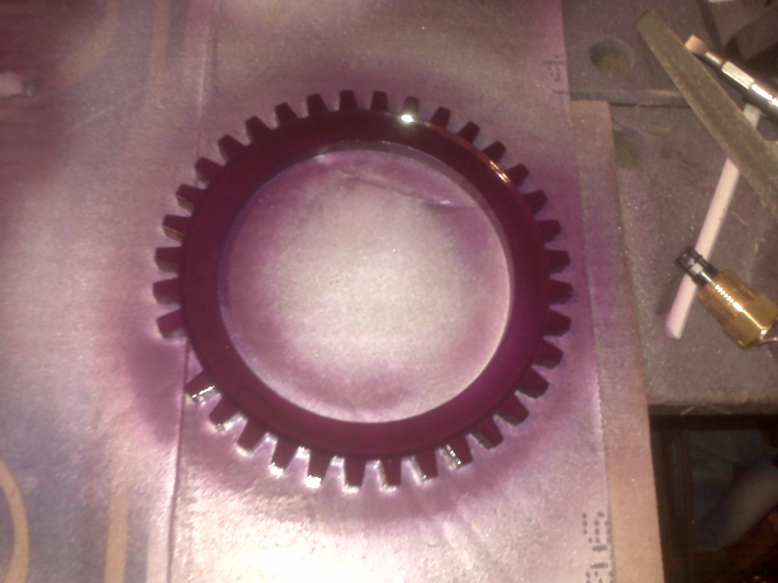
cleaned and painted the trigger ring
painted the distributor eliminator plug
put a coat of purple on the spokes
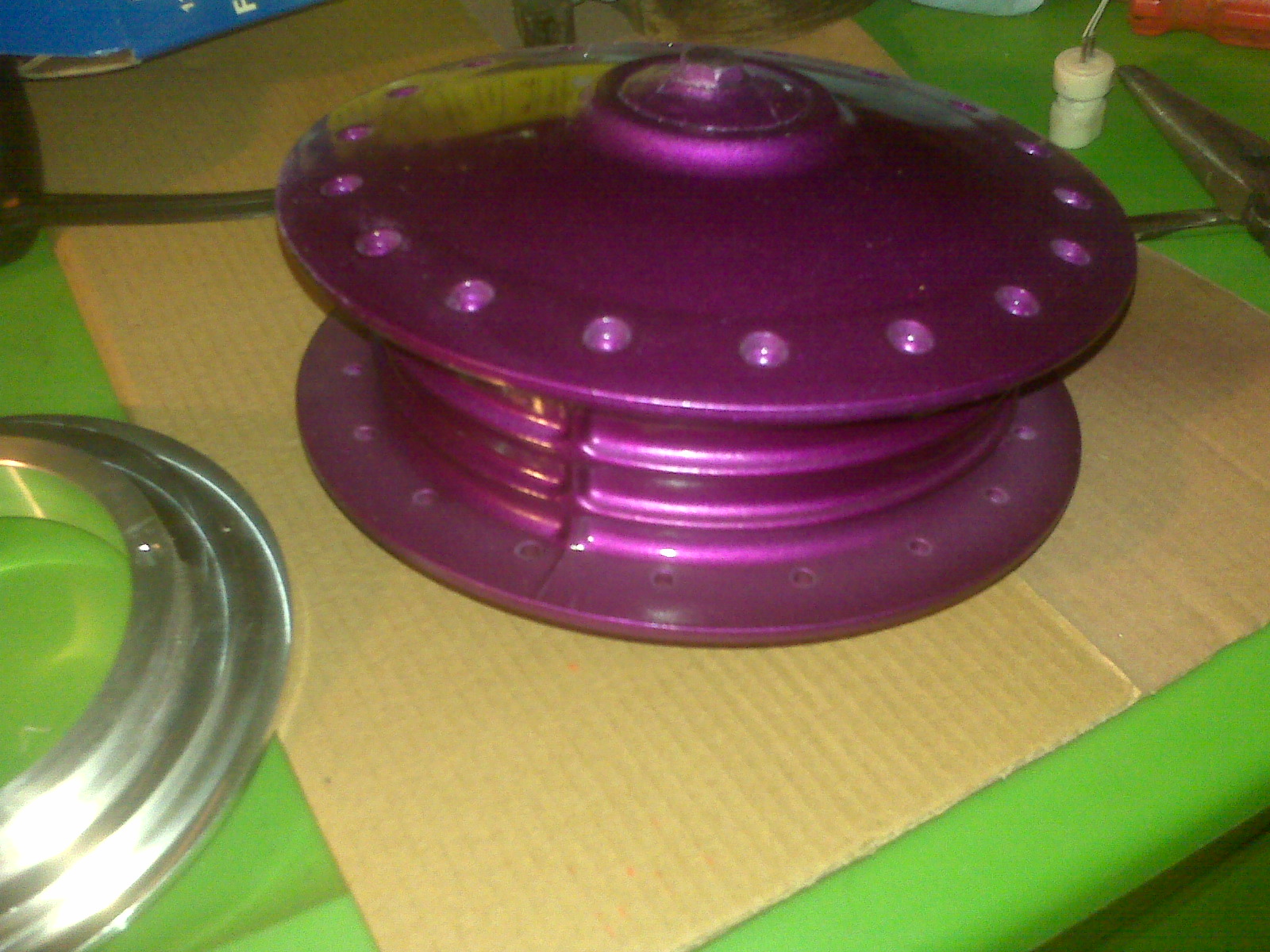
put the last coat of purple on the wheel hub
located and cleaned the distributor clamp (needed for plug)
put the body on temporarily so I could:
measure for the rear body brace

measure for the relay/fuse/ECU panel
estimated the thickness of the fiberglass where the ignition switch will go
measure the diameter of the ignition switch so I can acquire an appropriate holesaw
Perhaps the scariest, yet arguably one of the most important things was to make a master list of tasks left to complete the trike.
There are basically four categories:
1. Things needed to start/run/tune the engine
attach and adjust trigger ring
connectorize EDIS sensor
mount EDIS module
mount coil pack
cut plug wires as needed
wire relay/fuse board
mount ECU in weatherproof box relay/fuse board
wire all sensors etc to ECU
mount fuel pump and filler spout to tank
mount fuel tank (possibly higher off ground)
connectorize fuel pump
get fuel filter
connect fuel pump to filter and TB
build CLT sensor
connect vacuum to MAP; plug unused ports
mount O2 sensor
wire OS sensor module
baffle in stinger (for my ears)
2. Things needed to make the trike driveable/testable
build throttle cable
connectorize and install switch pod and speedo
install throttle
install grips
wire alternator light
wire oil pressure light
wire alternator to battery
mount and wire ignition switch
modify/build rear body bracket
mount relay board to body bracket
finish front wheel
3. Things needed to make the trike roadworthy/legal
wire headlight
wire tail/brake/turn lights
find front signal lights
wire front signal lights
find backup light
wire backup light
wire license plate light
find license plate
get and install front brake cable
mirrors
inspection
build footrest
install bumper
4. Things needed to finally finish the trike (mostly cosmetics)
fenders
polish rear wheels
through body filler tube
This as complete a list as I can imagine at the moment, but I’m sure I will remember other points along the way!
Wheel work continues
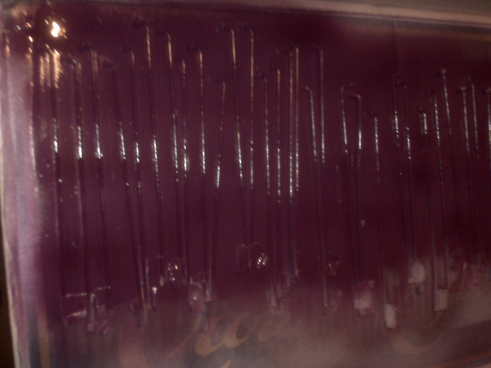
What’s more tedious than wire brushing 36 spokes? Cleaning them individually with acetone and taping the threads so you can paint them.


I also base coated and painted the hubs. Once the moving hub dries, I have one coat to do on the side hidden in this pic.

A coat of purple on the spokes and I’ll be ready to give lacing the wheel a try.
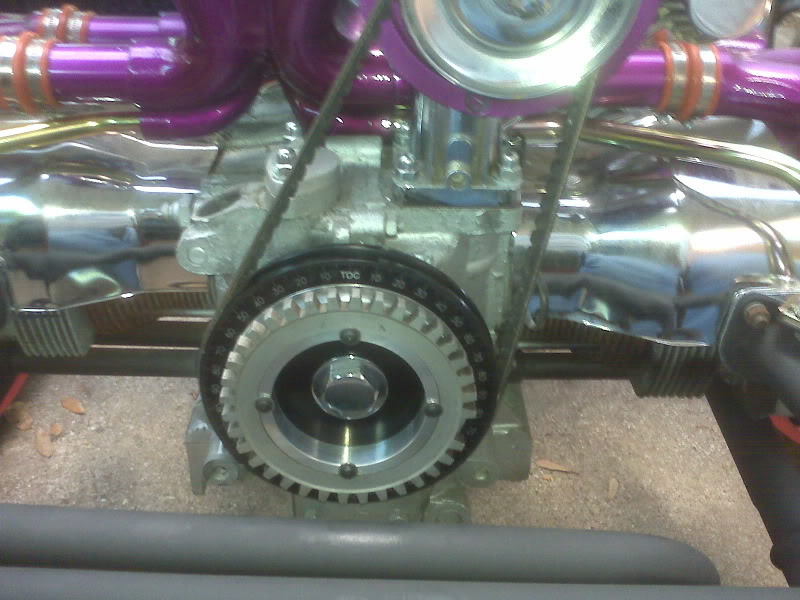
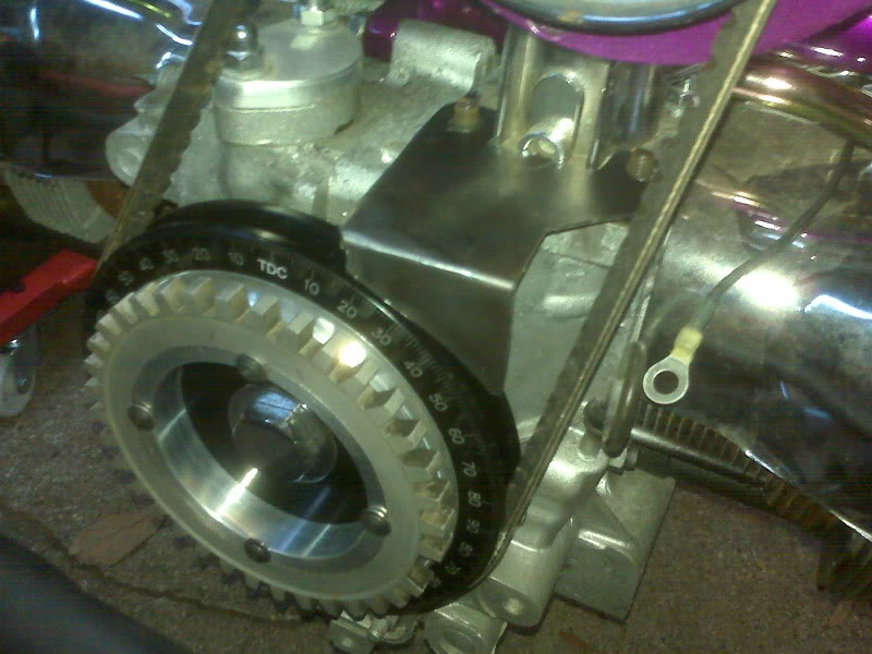
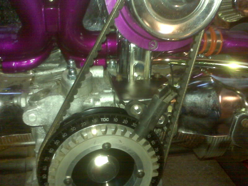
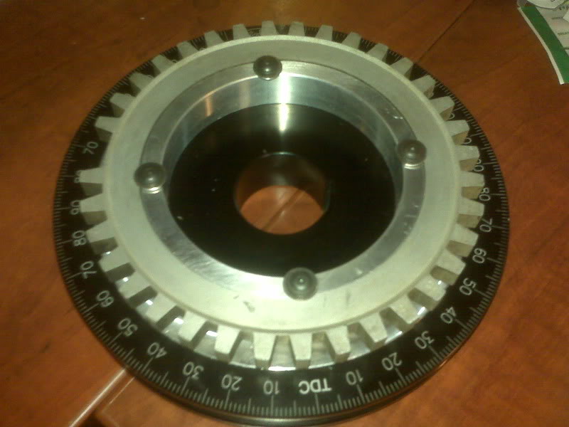
Trigger Wheel and EDIS Sensor
It was trivial putting in on, but it sure looks good.
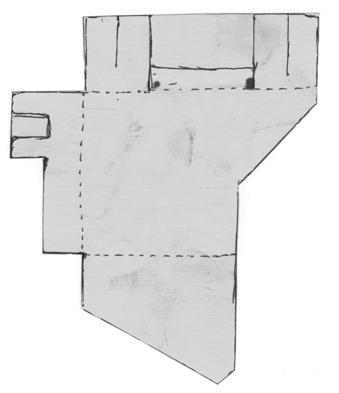
After a couple of trials by cutting, marking and folding, I arrived at this pattern for the bracket to hold the trigger wheel sensor. I marked it out on a piece of 16ga mild steel and cut it out with my benchtop bandsaw. I will attempt to never use anything else for cutting out this kind of stuff. It was fast and easy!
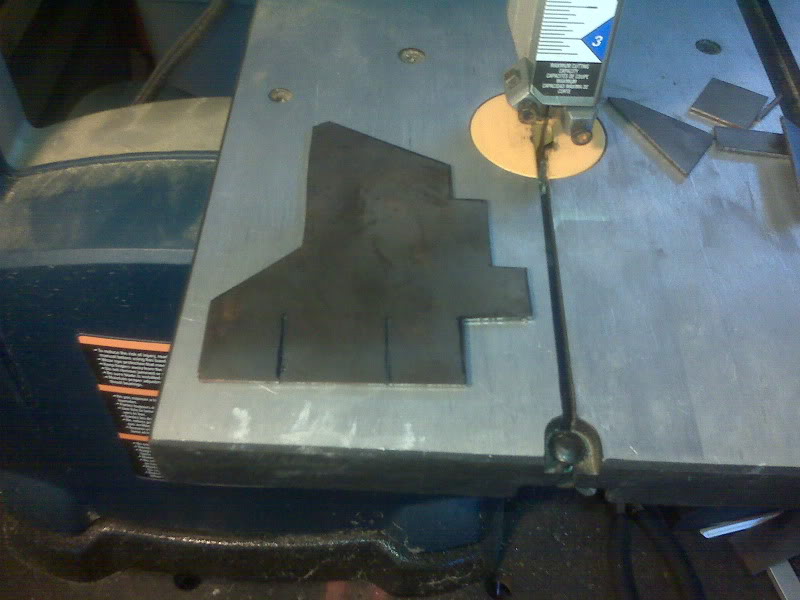
I proceeded to bend it into shape. As is often the case, the first bend was the easiest.
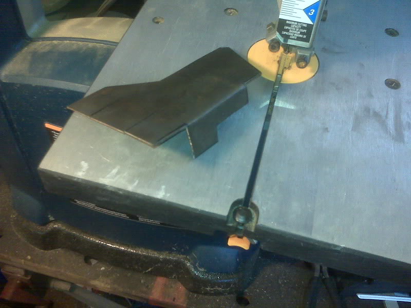
The next bend pretty easy, too. In my original plan, this bend would be 90 degrees, then the end would be cut to about 3/16″ to serve to stiffen the bracket in this dimension. Once the bend was made, however, I could not find a good way to make the third bend to my spec. I decided to fold the second bend flat, which will still stiffen the piece. Then the third bend was easy.
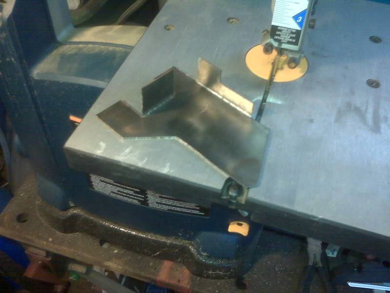
I cut a slot in the side brace and drilled the two top holes. It took a bit of grinding and tweaking to make it fit properly, as I expected since the pattern was made from very thin stock, compared to the final material.
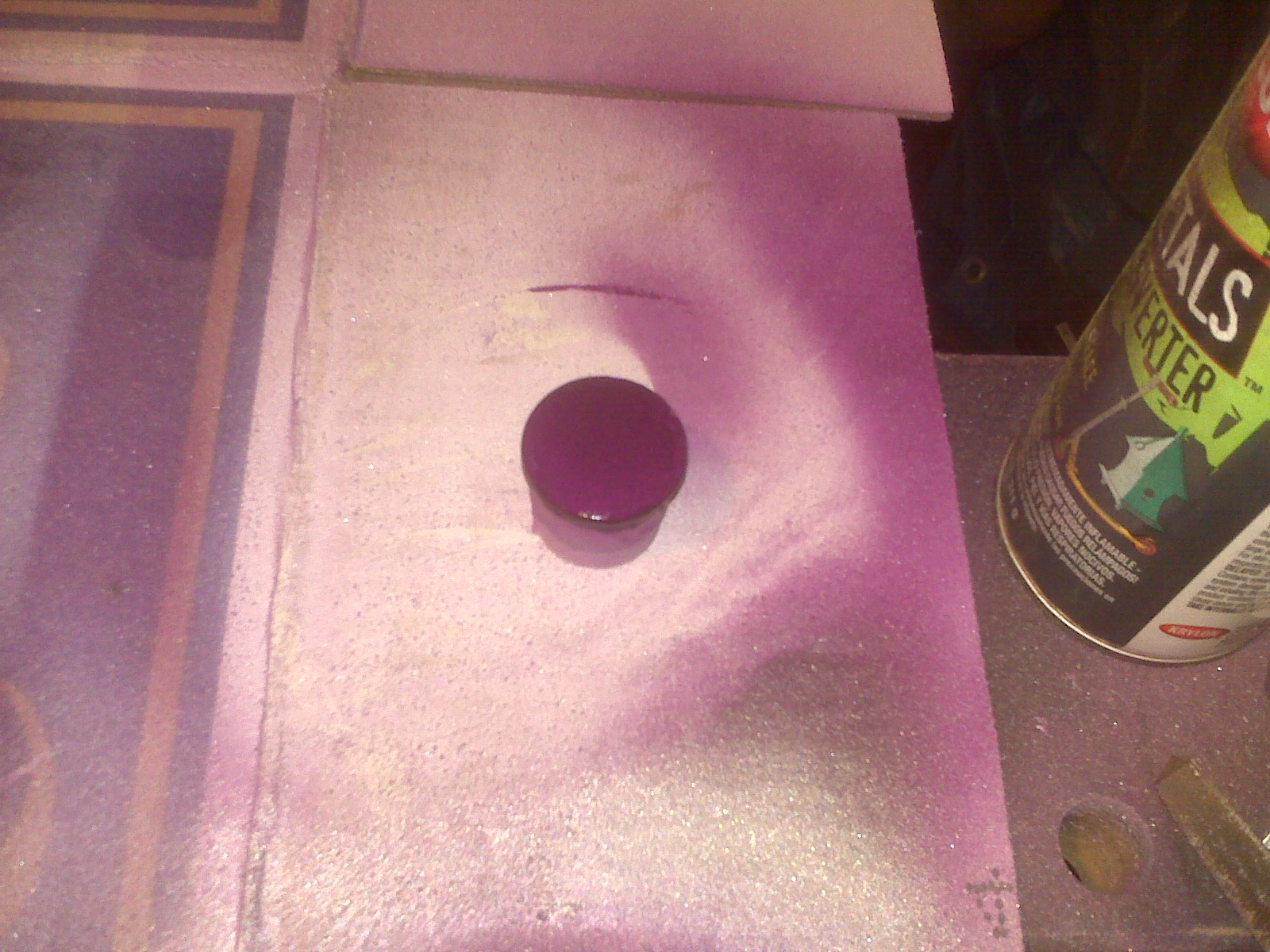
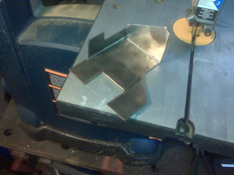
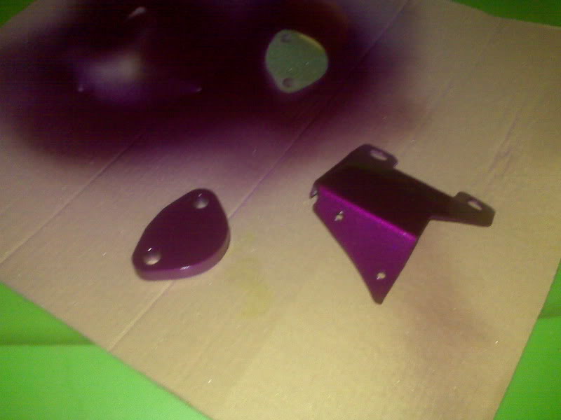
I am pretty happy with the final bracket. A shot of Krylon X-Metals converter and purple paint and it’s done. I would have painted the distributor plug, but I can’t seem to find it tonight. Story of my life… ![]()
I also worked on the front wheel.
It’s here!
The trigger wheel arrived yesterday!
I have scheduled this Friday off, the intent being to have a full relatively uninterrupted engine work day…