Shift linkage

I used 1/2″ weldable tubing to make a shift linkage.

The shifter came with a coupler that I used on that end. I had to take down the diameter of the tubing just a little for it to fit.

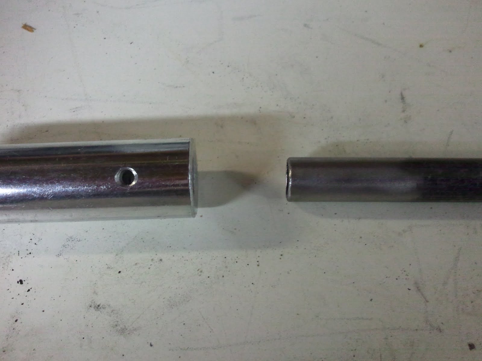
There is a roll pin supplied to stake the rod to the coupler. I may decide to use a more easily removable pin for the final assembly.

I used 3/8″ ratchet U-joints for the linkage. On the shifter end, I formed the tubing into a square end to fit inside the U-joint. I ground the face of the socket down to provide more surface area and to remove the chrome plating and welded it in place. On the male ends of the U-joint, I ground the tenon down to approximately cylindrical to fit inside the tubing and welded there.

The joints have a little more play than I had hoped. If they introduce too much play, I will try to tighten them up. If that doesn’t work, I may need to start over with better U-joints.

On the transaxle end, I used a shift rod adjuster but modified it. I hot forged the threaded end into a 3/8″ square to fit into the ratchet U-joint, shown here before welding.

The results look pretty good to me…

Still left to do is a support brace/bearing to stabilize the rod between the shifter and the first U-joint. I think I will use an appropriately sized bronze sleeve attached to a brace attached to the frame, although I have considered using Nylon. I will probably need this brace to be adjustable, so I will probably need to weld a tab to the frame for the brace to bolt to.

The New Checklist

So, not mentioned in the last post was the other reason I haven’t been working on the trike. I figured that whenever I tore into the shifter that I would be honor-bound to do a bunch of other things that would be best done with the trike body removed. I also figured that I would probably find other things that needed doing once I was in there. I was right. So, now I’m committed…

In no particular order:

1. When I put the new footpegs on, I did so without grinding off some old weld flashings and such that were largely unreachable with the body in place. Well, not only must I do that, I also need to repair the handlebar wiring harness. I managed to put the footpeg U-bolts over the wire and tightened them down. That it hasn’t shorted out already is only because the footpegs have not been in use.

2. I had not noticed before that the reservoir on the brake master cylinder was empty. Even more so, I had not noticed that the surface of the master cylinder appears to be wet with brake fluid. I think the reservoir has been bumped too hard and too many times. Besides, it’s not really designed to sit at an angle. I will look into a remote reservoir. I know the adapter for one is very simple.

3. I had a wiring issue that came from all the wires being tied down without any wiggle room. This resulted in at least one connector getting pulled from the back of the fuse panel and with the body in place, there was no reasonable access to properly correct the issue, so I ended up adding a “bypass” wire.

I need to restore the original wiring and maybe more importantly, prevent that from happening again. That may require cutting loose 197 TyWraps, rerouting and/or extending some wires and maybe even adding some bracing to the relay panel to keep it from moving.

4. I need to connectorize the speedometer sensor. It was one of the wires I had to unsplice in order to remove the body.

5. I also broke the (admittedly temporary) master power switch when I failed to notice yet another zarking TyWrap that connected it to the body. I have a really nice keyswitch that is supposed to be used for that, but I have been reluctant to saw the required hole in the fiberglass to install it.

5. Not even *one* of the wire tie pads that I stuck under the fiberglass body stayed. The wiring harness fell everywhere. So, no more self-adhesives or double-sided tape. I am going to epoxy some screws with fender washers attached to use as studs for standard metal wire loom clamps to attach to. I really want this to be the last time I have to address this issue…

6. Though this doesn’t necessarily require that the body be removed, it will be much easier with the body off, and that is to finally get the fenders on the trike. The old fender mounts will need significant modification to fit the new fenders, especially the left one which was itself suddenly modified in a collision untold decades ago.

7. The old fuel tank has had a lot of work done on it and still needs so much work that I might be time and effort ahead to replace it. It has at least one remaining pinhole leak that is currently plugged with an epoxy patch, I have a remote fill spout that will need a suitable fitting on the top of the tank and I have a fuel level sender to install. Rebuilding the tank to account for all these changes seems like a good idea, and might allow me to increase capacity at the same time.

The Long Anticipated Shifter

After months of mundane interruptions, including hair curling heat, I finally tore into the the new shifter for Puff.

Thus far, it appears that the method I devised for transposing one shifter location to the other is working.

First, here is the old shifter before I got started. At this point, I had already removed the shift linkage.

I started by cutting a template and bolting it in place where the shifter would go.

Then I welded a couple of temporary braces between the plate and the frame.

Then I could remove the bolts and cut out the old shifter.

I forgot to cut out the template plate for the parts on the face of the disassembled shifter box. I drew in the shape from measurements, cut out the relief and bolted the shifter box on the check the fit.

At this point, I realized that a) I needed some bolts and b) chances were pretty good that the hardware stores might close early on Labor Day, so I skedattled.

When I returned, I made a plate that would become the new shifter mounting plate.

and bolted the entire assembly together, template, shifter and mounting plate, with my new bolts, seen here from the back.

I measured, cut and fit two braces to attach the mounting plate to the frame…

… and welded them into place.

I removed the shifter box…

Cut off the temporary mounting, reassembled the shifter and this is what it looks like now!

What’s left is to build the linkage. It will basically be a few lengths of 1/2″ tubing connected by U-joints.

The shifter handle is held in place by a split ring. When it’s removed, the body should easily fit over the shifter, then the handle is reinstalled.

After playing with the shifter some, it appears that the reverse lockout may be more trouble than it’s worth. It requires enough effort to engage that it is very difficult to do with one hand *and* apparently you have to press the release to get *out* of reverse as well.