Category Archives: N5HRK Amateur Radio

My ongoing adventures in the world of ham radio

Reach For The Stars

Ok, maybe not that high….

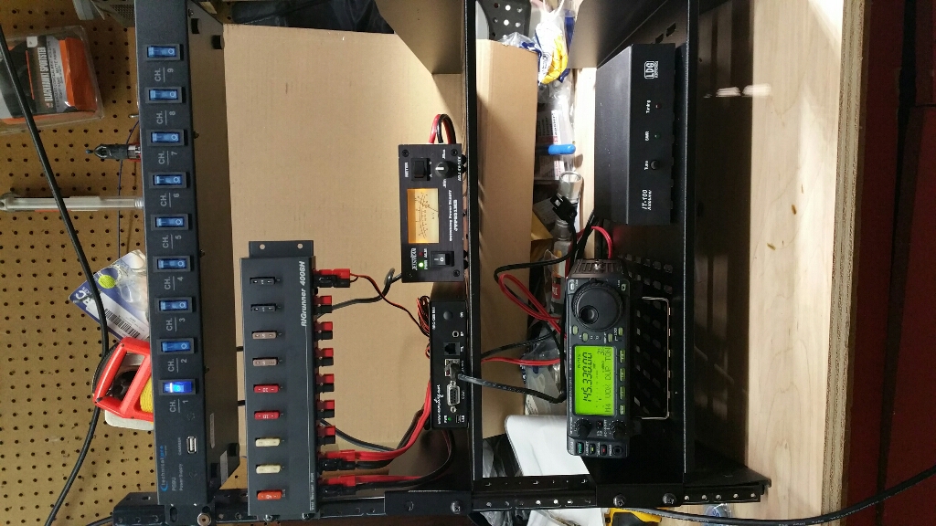
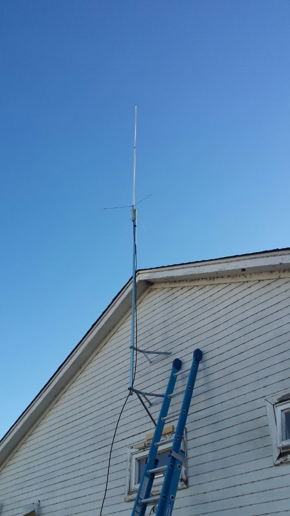
Due largely to my difficulties in reaching in to repeaters in the DFW metroplex, I have been looking somewhat into erecting a tower. While my immediate plans are to put a Diamond X300 up on the top of it, having a structure for wire antennae or a tower mounted camera would be nice, too.

The tower itself is expected to be $1500-2000, depending on installed height.

Universal Tower has an aluminum self-supporting tower design that seems to hit all the bullet points. They use a system wherein they design a tower from 30 to 100 feet high, with wind load ratings of 3 to 35 square feet, using modular 10 foot sections of various sizes. They have straight, tapered and top sections in 11, 14, 18, 22, 26 and 30 inch widths. The heavier ratings are shorter towers with wider sections. The straight sections are, duh, a straight section of that width. The tapered section are of that width, but they taper down to the next smaller size at the top. The top sections are finished off like you expect a top section to be, with a conical bit and a place to put a pipe or tubing mast.

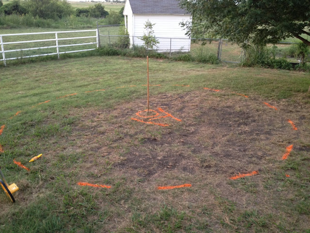
I have analyzed the sizes and chosen a starting point of the 9-40 tower, 9 square feet rating, 40 feet high. The entire system consists of a big block of concrete (4 x 4 x 4 feet, which would weigh just short of 5 tons) in the ground with a 22 inch base unit, a 22″ tapered section, an 18″ tapered section, a 14″ tapered section and an 11″ top section. The tower itself is about $1115, not counting the concrete and digging the hole for the anchor.

If 40 feet is not enough, I can add an 18″ straight section between the 22″ tapered and the 18″ tapered for $270, raising the assembly to 50 feet. Continuing, I can add a 14″ straight section for $155 to make the 50 into a 60 and a 22″ straight section for $409 to make the 60 into a 70.

As the height goes up, the wind load rating goes down, 9 square feet, to 7, to 4 and to 3. The 70 foot design is the tallest they allow for the 22″ base. The next size base, 26″, requires a bigger concrete base (4.5 x 4.5 x 5.0 feet) and the 40 foot tower, while rated for 23 square feet wind load, starts just a little cheaper than 22″ 70 foot. Furthermore, the 70 foot tower with the 26″ base only gets 1 more square foot of wind load rating.

I’m guessing a 50 foot tower is likely what I will need to get a better signal into the metroplex. The antenna itself is 10 feet tall and could be mounted on a 10 foot mast at the top of the tower, so the base of the antenna would be at about 58 feet and the top at about 68 feet.

I have a couple of emails out to get quotes on the concrete and the digging. I suspect that digging in our area will hit rock only a little way down, so mechanization is probably going to be a requirement.

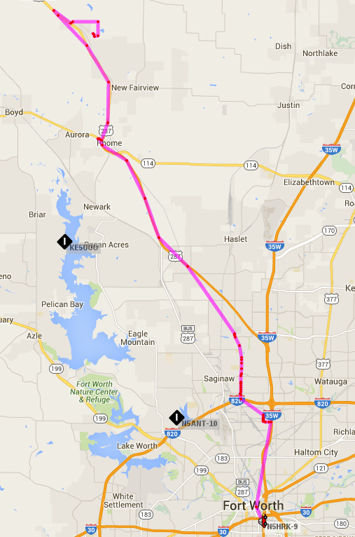
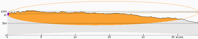
There is another variable that I thought wise to check on. The runway at a nearby grass strip airport points pretty much directly at our house. On the fcc.gov website, there is an online tool called TOWAIR wherein you can plug in your coordinates and some details about your proposed tower and it gives a PASS/FAIL on whether your structure needs to be registered with the FAA. It basically calculates the maximum height that a structure can be, based on some rules and specifications. Because this little airport has a runway in excess of 3200 feet and is designated for Public use, a structure within 20,000 feet must fit in a 100:1 glide slope. For every 100 feet farther away, the structure can be 1 foot taller.

When I plug in the coordinates where the tower would be and specify a total height of 70 feet, the tool returns the following failure message: “FAIL SLOPE (100:1) FAA REQ – 0.0 Meters (0.0 Feet) away & exceeds by 11.0 Meters (36.0900 Feet)”

Short version, 70 feet is 36.09 feet too high.

Now I am almost certain this does not mean that the tower would be prohibited, only that it must be registered. Further, it may need to be painted or lighted. I have much research to conduct.

By easter-egging various figures, I was able to determine that a height of 32 feet 9 inches would not need registration. Also, although it would be fairly impractical, moving the tower to the farthest point away from the airport and still on our property is not far enough away to change the permitted height.

While I was snooping around with antenna heights and locations, I punched in the numbers for an 80′ tower on a property not too far away. It is far enough away to clear the requirements with 9.8 feet to spare.

Harald Blaatand Comes To Visit

The good king Harald came bearing gifts.

The Yaesu BU-2 is a Bluetooth adapter for, amongst others, the FTM100DR. Other than the 10 screws required to get into the radio, it was very simple to install.

First, you need to get it out of the box. A tiny box.

upload_-1 (5)

The box is full, just not with much electronics.

upload_-1 (6) upload_-1 (7)

All that paper can summarized thusly: Yaesu made this, it meets all kinds of standards, most of which have nothing to do with the device’s function, and detailed on one sheet, in 22 different languages, “don’t throw this away in your trashcan.”

The card itself is a little bigger than a quarter. Curiously, there is a tiny pushbutton on one edge of the card, but it’s not reachable without pulling the front over off and it is not mentioned in the directions. Shrug.

upload_-1 (8)

The inside of the radio is nice and clean.

upload_-1 (3)

The card plugs in near the front of the radio, where the plastic front wouldn’t shield the signal.

upload_-1 (10)

Once installed, the settings (split into two menus for some reason) suddenly work. Defaults seem to work fairly well.

I paired it with my LG HBS-750 headset. I have others, but that one was handy. It paired quickly and easily.


upload_-1 (11)

Operationally, the “answer” button on the headset serves to toggle transmit. Press to talk, press again to stop. Interestingly, the current menu option was “Momentary”. The other option, “Toggle”, made the transceiver stick in transmit. I suspect it’s just a difference of opinion between the radio and the headset. I will continue playing with it.


APRS

Short version, pretty cool stuff…

I had never really thought much about APRS. It seemed like the only application getting much attention was vehicle tracking and I think our privacy is compromised enough already.

However, I came across a propagation map website, which was populated using APRS data. It can be argued that it’s not very scientific, basically building a propagation map based on the location and signal strength of received APRS packets but I don’t think it’s completely without merit. In any case, my interest in how this works lead me to experimenting with the APRS settings in my FTM100DR.

Just getting it receiving data is trivial, basically enable the modem and set the frequency to 144.390 simplex. There’s not much more to getting it transmitting beacon messages. After a brief trial last night, I set it up to send every 3 minutes this morning and tracked my commute. As luck would have it, I-35W was shut down for a while and I had to take an alternate route. Also, at one point, I turned it off as I got into solid range for Fort Worth repeaters, but once I was on said alternate route, I put it back on APRS for the fun of it. Between that, the 3 minute update interval and I presume an occasional lost packet, it looks like I went offroad or maybe airborne occasionally.

aprs-track

As I researched APRS, I found a lot of references to it not being just a vehicle tracking facility. In fact, a number of people seem to think it the acronym is Automatic Position Reporting System, rather than Automatic Packet Reporting System. Granted, GPS equipped mobile transceivers make mobile location data easy to share, but that is not all it’s good for, i.e. the afore mentioned propagation map. There is a plethora of information at www.aprs.org, a pretty good starting point.

As for my own homework, the quickie setup I have on my FTM100DR now means it is either doing APRS or voice. In fact, I have to remember to turn off the beacon when I go back to voice, lest I hit voice repeaters with APRS packets. I can’t imagine that’s the only way to set it up. Longer term, I can see it being fun to set up a permanent beacon. Just need a compatible transceiver and a TNC/PC combo. I see another Raspberry Pi project in my future.

Elevation Profile

There are a couple of free elevation tools on the internet. I don’t like the conclusions, but I guess it’s better to know.

FreeMapTools has an Elevation Finder tool. With it, one can easily check specific elevations anywhere you click on the map. There is also that less intuitive but better suited Hey What’s That website. I did profiles of my path to repeater with both Elevation Finder and HeyWhatsThat. They seem to agree that my 885-ish foot home elevation is no match for the 1000+ peaks between me and the 949 foot repeater antenna.

path-rpt

Note that the highest elevations are within 3 to 5 miles of home.

The only good news is the orange highlighted area, particularly the skyward piece. This is the calculated propagation of a 145MHz signal between these two points. The fact that I can hear the repeater fairly well is also promising.

At this point, more gain may not make nearly as much difference as more altitude.

The calculated altitude needed for a completely unobscured point to point view would be 170 feet above ground on my end, so lets hope it doesn’t take that much.

Rack’em Up

I finally put together a desktop 19″ rack that I have wanted to put together to put all the RemoteRig Radio end equipment into. It went pretty quickly. The shelves came with hardware that didn’t fit the threaded holes in the rack. Luckily, I did have enough of the right size to assemble everything, though I need a few more to make all components attached with the right number of screws.

upload_-1

Please pardon the workbench.

At the top is an AC plug strip with individually switched outlets. At some point, I hope to have some other equipment in this rack, so the lone device connected to it on switch 1 will have buddies.

Switch 1 powers the JetStream 25A switching power supply.

The DC output connects to the input of the RIGrunner 4008H distribution panel. I connected one of the 25A outputs to the Icom and one of the 1A outputs to the RemoteRig. I made up a spare power cord to use with either the Kenwood TM-731 or the Yaesu FTM100DR, as they both use the same T-style connector.

After that, it was just connecting the grounds and antennas back to it. For the time being, I have left it in the center of the workbench because it’s permanent home still needs a bit of work to clear out. We’ll see what the evening allows.

Altitude is Relative

I have had some trouble getting a signal all the way back to Fort Worth. In fact the repeater I frequent is pretty much exactly 28 miles away. 50 watts into a 6.5 dBi omni antenna *should* look like 136 watts, but that doesn’t account for the hillside between here and there.

Our property is downhill from the street, but today I used a builder’s level to quantify what I believe to be a significant factor in my limited range towards Fort Worth.

For those unfamiliar with a builder’s level, it’s a piece of surveying equipment used most often to ensure structures are level over long distances, particular stuff like driveways or drainage ditches or houses. I first used one when we were building a sand pad for an above ground pool.

IMG_01065

The ground within this circle is 10 inches lower on the left side than the right.

You set up the level on it’s tripod and either leave it where you put it throughout the project or mark precisely where the legs are. Using the bubble level on the device and the adjuster wheels, you set the unit itself level, then using the graduated measuring stick, you look through the little telescope and get the height of the measured point relative to the level plane described by the tool.

IMG_01064


IMG_01061

This pic shows the view through the view scope. The ‘6’ is very dim, but in this view, the ground at the measured point is just under 6′ 8″ below the crosshairs in the level.

Well, I did not use the measuring stick because I was looking for much more of a thumbnail measurement (and it’s a pain to do without an assistant), but I set the level up on the street out front and took a sighting off the antenna on the workshop.

The level is 5 feet up from the street. Once set, the level sighted the workshop just a few inches below the roof peak. Go down 5 feet from there and it’s about the bottom of the antenna mast.

upload_-1.12

So… the antenna mast is essentially sitting at street level, meaning the base of antenna itself is only about 9 feet above the ground in the direction of the repeater.

Even with a beam, I will probably need to get some more height.


A Mostly Good Day

Lots of little things today.

On the way out of the neighborhood this morning, I had my little SDR running, centered on 145.33. At the house, I saw a pretty strong birdie at exactly 144.000 and it never went away all the way to work, so I presume it’s an artifact from the laptop or perhaps in the radio itself. There was a tiny peak just above the repeater at 145.4125, but it went away by the time I got out to the truck, so it was probably something in the kitchen.

rfi-1


Interestingly, Oncor called me today with an update. Basically, my incident has been assigned to an RFI tech. I can expect to hear from them maybe Friday, but probably next week.

There was talk on the repeater today about a short Fusion Digital net right after the regular Six Shooter Net, so I put the FTM-100DR on the workbench so I could use the big antenna and have the best chances of joining in.

On the FM net, I tried to check in on *every* round and was never heard. I guess I need a beam or some more altitude. With the assistance of GoogleMaps, I have determined that I am 28 miles line-of-sight from the repeater. I am considering a three element beam. It would definitely have enough gain going that direction and would likely be wide enough to reach other Fort Worth area repeaters as well.

I eventually gave up and used the time to upgrade the firmware in the radio. I had plenty of time because it was the first time for a particular lady ham to run the net and people came out of the woodwork to check in for her. By the end of the net, she broke both standing records for length of a Six Shooter Net by three minutes and number of unique checkins by ten, even without mine!

So, the FTM100 firmware update procedure is split into three separate elements, the system, the display/control panel and the DSP. Before any of them, you connect the data cable to the PC and run the update program. It shows directions, which are also explained in an accompanying PDF in greater detail.

For the main firmware, you remove power, set an update switch reachable behind a rubber plug on the top of the radio and apply power. The weird part is that the radio in this mode shows no signs of life. You just click the OK and it starts loading. After it finishes, you are to remove power, set the update switch back, power up, perform a factory reset then verify the version.

The panel is different in that you hold down a two key combination on the panel as you power on the radio. It puts the radio into a mode specifically for panel updates. Then you flip an update switch and press a reset button reachable behind a rubber plug on the back of the control panel. Click ok and it starts loading. When it finishes, you again power cycle, do a factory reset and verify the version.

The DSP is similar to the panel. You hold down a different two key combination on the panel as you power up, then press a key on the panel to get to the DSP update mode and click OK. Interestingly, the DSP update didn’t claim to need a factory reset and definitely showed to be updated by the version numbers.

After the factory reset, you lose the callsign and all your channel memories and any other settings. It’s probably best to backup all to an SD card before the updates then restore from SD afterwards. In my case, I had both the SD card and the programming software.

So far as I can tell, the updates didn’t fix anything that I was aware of 🙂

So by that time, the record-smashing Six Shooter Net on FM had concluded and they had anyone who could do digital do a quick checkin with their location. Not surprisingly, I couldn’t make it, but 16 others did.

Oncor RFI Saga

Tiny update:

Thank you for contacting Oncor regarding radio interference. Your request has been assigned to the appropriate department. One of our representatives will contact you within the next 2 business days.

So, maybe something will come of it afterall…

Curious Noise, Cont.

Actually, before I update on the noise, I spent literally single digit minutes remotely mounting the control head of the Yaesu.

When I got the radio, I also got the  MMB-98, a universal(ish) suction cup mount that fits several models of Yaesu radios.

I moved my GPS to the windshield, to the right of the rearview mirror, which left this space open on the dashboard. The mount uses a single screw through a pad of fixed radial teeth to provide a secure and adjustable angle. Unfortunately, there is not an angle that precisely matches the angle of my dashboard, but it is reasonably close to level. More importantly, it’s WAY easier to see and operate up here than it was down there.

I am quite pleased.

So, the noise…

I asked on a Thursday night net if there was anyone near my experiencing the interference. There are hams nearby, but none really close. However, on person suggested contacting Oncor Energy about the noise, as such noise is frequently power line equipment related, generally easy for them to locate and resolve and they are apparently pretty good at it.

I chose to contact via a general email. In short, I explained how I noticed and my investigations thus far. For what it’s worth, their email robot replied pretty quickly, assigned me an incident number and suggested that the request will be processed within 48 hours.