Trigger Wheel Dentistry


Short version: It worked.

Long version: I varied the plan slightly, based partly on not having the right size drill bit. I didn’t have a small bit to use for plan A, so I used a 1/8″ bit and, since I happen to have a gob of them, a 1/8″ x 3/8″ steel rivet.

I centerpunched the appropriate spot and drilled a 1/8″ hole about 3/16″ deep in the edge of the wheel. I drilled another 1/8″ hole to intersect the first one. I inserted the rivet to the right depth, which was scant less than bottomed out. I used a center punch to stake the rivet in place. I cranked up the torch and filled the space in with brazing rod through the intersecting hole. Easier to do than to describe, I think.

After that, a little grinding, filing and wire brushing and it’s got another decent tooth.

I used what I’m sure will turn out to be temporary spacers and bolted the wheel to the crank. It took a couple of times to get it adjusted close enough to start, once it was going, Buzz had what was actually a pretty ok idle. All four pipes hot!

The signal is a solid 1.8V, so I gained quite a bit of signal power. I suspect the timing is still a little off because I can’t get him to rev over about 3500 RPM and by then the advance needle in MegaTune is swinging wildly. Sounds kinda like he hits a rev limiter that recovers kinda slow. The RPM is nowhere near the rev limiter settings.

Most importantly, I now seem to have reliable ignition, so next time I get to work on it, I think I will button up the ECU and EDIS module into their permanently attached locations.

As for the trigger wheel, what’s left is to solidify the connection to the crank. The wheel sits just about perfectly on two nylon spacers that I got at the hardware store. At this point, the plan is to get a dowel pin long enough to secure both spacers to the crank, use the timing light to get the wheel within the timing adjuster range of dead on, then use another smaller dowel or roll pin to secure the trigger wheel to the spacers. The roll ping will reside under the fender washer under the bolt that holds it all to the crank.

Let the tuning begin!

More chips


Sometimes, I am such an id10t.

I spent a couple hours last night making a new trigger wheel from a scrap 3/16″ angle bracket that was in the junk box that came with my Stires trike. I used a 3-1/4″ hole saw in the the drill press to (slowly) cut out the disk, the bolted the current disk to the blank and hand ground it to size. With the original still bolted in place as a template, I center-punched for each hole to drill. I took the original off and proceeded to drill all 36 holes. Once the holes were drilled, I fitted a 3″ cutoff wheel to a drill arbor and used that to cut slots into each hole. A little judicious grinding, wire brushing and LOTS of filing to get the teeth in pretty good form. They are not CNC clean, or even manual rotary table clean, but they are very nice for generating timing pulses.

Well, if I needed a 36-2 trigger wheel, it would be good.

My excuse is that by the time I was ready to remove teeth, my brain was on autopilot and somehow removed two teeth instead of one. I didn’t even realize it until I was showing Toni the fruits of my labor.

In the interest of avoiding a shopping trip, I have a plan that may be able to salvage this wheel, a plan that is very much like applying a dental implant. I will drill a hole in the edge where the extra missing tooth should be, use short bit of fluxless welding rod as a reinforcing pin and braze on a similarly drilled replacement tooth. Grind and file the tooth to shape and we’re back in business. Even with brazing, the replacement will still be a lot more ferrous mass than a missing tooth or the previous wheel. If it doesn’t work out, I’ll be headed to Norton Metals.

Sparks…. good. Timing…. bad.


It’s Monday. I did get to work on Buzz for a while on Friday evening, but have only just now been able to sit down and bang out an update.

After giving up on the search for a local source for terminals and boots to customize my existing salvage spark plug cables, I elected to purchase a nice set of wires and hack the salvage coil connectors onto them. It actually worked out quite well.

Once I had the wires, it was a pretty simple matter to snip the old coil connector off and gently pull the connector out of the boot; it’s easy to bend and the brass won’t tolerate much bending. Then I carefully wedged the crimp apart and removed the old wire. I used needlenose pliers to bend the tabs back into a shape that looked usable, a little curve ready to bite the cable.

I cut the new wire to length, plus about an inch. Used the dielectric grease supplied with the wires to lubricate the wire and threaded it through the cap. I stripped off an inch of the insulation, folded the conductor back and manually crimped the terminal on. Crimping like this is pretty much by definition not as reliable as using a proper crimping tool, but they passed a moderate pull test. I saw now point in breaking it on purpose.

I routed the wires and installed them. Once the wires were in place, I secured the coil with nylon wire ties.

I put the rest of the system back together and tried to start Buzz up. It was a little cool out and as expected but not as hoped, I had trouble getting it to run well enough to even idle. I was able to get it to run enough to heat up exhaust pipes. Cylinders 1 and 2, warm. Cylinders 3 and 4, cold.

I played with the timing by finding TDC on #1 and adjusting the trigger wheel. Again. I toyed with the wheel and I think finally have a unifying theory of the problem.

Alert (obsessive) readers may recall that I voiced some concern about the signal voltage from the VR sensor and my thin little trigger wheel. I put my meter in bargraph mode and watched carefully as I cranked it. The displayed digits dithered between .484 and .486 volts, but the bargraph indicated a swing of .1 volts. I suspected I would know the cause of the voltage swing.

With no helper available, what I did next was kinda hard. I pulled the stock ignition fuse (well, technically my replacement of it), the fuel pump fuse and unplugged the ignition coils. I wire tied a wrench to the starter button and placed the meter where I would watch the meter and the gape between the trigger wheel and the VR sensor. I pushed the fuse in, which started the engine cranking. Sure enough, the gap between the trigger wheel and the sensor, as small an eccentricity as it may be, correlated with the swing in the output voltage.

The information in the MegaManual indicates that the EDIS module doesn’t “arm” the counter until the signal exceeds .5 volts. I know that there could be some tolerance, but the tolerance could just as well require .6 volts as .4 volts. In any case, I can definitely see where the EDIS module could be missing pulses and screwing up the timing something terrible with this bad information from the sensor.

The best way to increase the signal is to add mass to the trigger wheel. I see metal chips in my future.

EDIS fall and rise


I discussed the cylinder 3 issue on the Yamaha XJ Owners list. I first wanted to verify that I was not making any assumptions about the actual firing order of the coils, whether the coils do indeed fire alternately, as opposed to sequentially. In other words, if the firing order was something like 1-4-3-2, it would need to fire the two coils in a left-left-right-right sequence, but with 1-2-4-3, it would be left-right-left-right. The EDIS module definitely expects to fire left-right-left-right and if the bike was expecting left-left-right-right, I would need to swap some plug wires around to account for the “change” in coil firing order. However, with all that was suggested on the list and my own understanding of things, I think the coils are firing in the proper order. Besides, it did run on three cylinders at one point.

Another suggestion was that the EDIS system may not work well with the higher impedence stock coils. One lister wrote:

What does the EDIS system expect the coil primary resistance to be? I think that the stock coils are about 3 ohms. When I looked up some replacement coils for an EDIS system from Accel, the primary resistance was 0.5 ohms. The higher resistance of the stock coils could cause the EDIS ignition to not produce enough current to fire the coils consistantly.

Intuitively, I would think that since EDIS module grounds the coil connection that it would power a 3 ohm coil as well as a 0.5 ohm coil. Upon analysis, the suggestion does have merit. Ohms law dictates that a 0.5 ohm coil would pull 28A from 14V, but the supply fuse for the coils and the module is a 15A. Yes, in brief pulses like the ignition system uses, the fuse could probably tolerate nearly double it’s rating, but it seems unlikely that they would do it that way. More likely, they are limiting the available current with an internal series resistor. That series resistor plus the already much lower current draw of a 3 ohm coil could combine to prevent the 3 ohm coil from getting enough current to make a good spark.

So, I stopped worrying about it until I could get a Ford coil to work with.

I stopped at a pull-a-part place on the way home Monday night. They close at 5:30; I arrived at 5:15 with warnings that I only had about 10 minutes. I found the coil on the very first car I walked up to. Four little bolts and two snips later, I’m at the counter laying down $27 for the coil, connector and plug wires. On the road home by 5:25.

So, I clean it up and put a compatible connector on it. I connected one plug wire and put a handy sparkplug (out of the Sportster trike) in it and pulled the fuel pump fuse. I grounded the plug on the engine and cranked. I got a teeny little unimpressive spark and an unhealthy dose of dashed hope.

Then I remembered that these sorts of coils like both plugs connected. The high voltage circuit is from one coil secondary lead to the plug, across the gap, through the block to the other plug, across that gap and back to the other secondary lead. So, I dug around and found another suitable spark plug. Lucky for me the Sportster is a twin. I connected both plugs to the 1/4 coil outputs and grounded both plugs to the engine. This time, when I cranked it, I got a nice fat blue sparks with clearly visible orange plasma. *AND* about every third spark or so, a 15mm long lightning bolt jumping BETWEEN the two spark plugs, as in from one plug’s electrode to the other plug’s electrode.

Faith is restored.

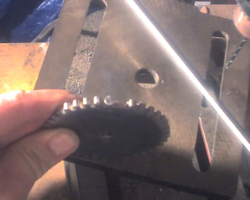
I have found that “Yamaha” is apparently Japanese for “hidden relays” and I will need to relocate another relay, the function of which I have yet to ascertain, one that once resided between the two stock coils. With the mystery relay out of the way, the Ford coil fits very nicely in the space where the stock coils were, even with all four plug wires attached.

On the car, the coil towers “faced” upward, looking like a square distributor at one end of the engine. I have them facing downward. It looks like it was intended to go there.

The remaining work will be wiring, both to the EDIS module and to the plugs. The Ford wires, besides being way too long, have molded on plug ends, I would need to replace these ends, which wouldn’t be too bad a job. They need to be radically shorter anyway, probably none longer that 30cm or so. I’ll have to get the screw on contact tips for my plugs.

The stock XJ550 plug caps appear to have 10K resistors in them, but the monster spark was off resistor wires, so I think I can use some sort of crimp on plug terminals and not worry about resistor caps. Hopefully, I can find a pair of 90 degree caps and a pair of some lesser angle, but straight connectors will work for all four if I must.

Better, yet worse


I got to work on Buzz some last night afterall.

Short version:

Yesterday while testing, the pipe for #3 was cold, the others hot. Injectors check out fine with low pressure bench test. Reinstalled throttle bodies with new silicone intakes and with air filters fitted. Starts and runs on cylinders #1 and #3, pipes for #2 and #4 cold. Verified that all four plugs have spark.

Long version:

I started the bike and ran it for a few seconds, assuming that if the injector for cylinder #3 was not working, that intake tract would be dry. I then pulled the throttle bodies and found that #3 was indeed wet with fuel. I suppose it’s possible that it could be old fuel, but all 4 intakes appeared to be similarly soaked.

I used the pump bulb for a marine fuel tank to put a little air pressure on the fuel rail and operated each bank of injectors with a 12V battery. My fuel pump test power connector is of the proper gender to facilitate testing the injectors. Chalk one up to serendipity. Or maybe my subconscious is better at this than I am. Could explain some other things. Anyway, all four injectors operate identically under this low pressure test, so I don’t think #3 was clogged.

I wanted to shorten the intake tracts, partly to help keep the soft parts short and rigid and partly to make more room for the air filters. Cutting the silicone reducers for cylinders #1 and #4 was easy, just make them shorter. The other two, however, have to also take off a bit of an angle. It turned out to be pretty easy to cut them at a suitable angle. I cut the TB end first, then very scientifically eyeballed the length of the straight ones and cut the intake ends of the #2 and #3 to match.

Somewhere in the months between the first fitting of the neoprene reducers and getting Buzz started a couple weeks ago, I lost one of the larger hose clamps and had to replace it. The 2″ clamps I ordered with the silicone reducers are too wide to fit the throttle bodies and the 1.5″ ones don’t compress enough to fit the intake side, so I had to reuse the hose clamps. Unfortunately, the odd one, the one I had lost and replaced, was about 1/8″ too short to fit the silicone intake. It took a lot of tongue biting and eye crossing to get it to catch and clamp down, but I finally got it.

The throttle bodies are a good inch closer to the engine and the short silicone reducers are significantly stiffer than the neoprene was. I repositioned the support bracket and still had to use a longer bolt to reach, but now the throttle bodies are almost rigidly mounted.

I had to reposition the fuel filter to make room for the #1 air filter. Basically, I just swapped the hoses and put the short one between the tank and fuel filter and snaked the long one between the air filters #1 and #2. The air filter for #4 was still a tight fit to get in place, but once there, it clears the frame that it used to hit.

After reconnecting everything and restarting the engine, it seems that cylinder #3 is working, but now #2 and #4 are not. This is beginning to be a very frustrating problem.

I have one more desperate thought. The fuel I’m using for all this could be kind of old. I think I will drain the tank and refill it with fresh. I think I will also do a compression check. My first thought is that the compression wouldn’t have dropped just because I added EDIS.

Normal troubleshooting would demand that the ignition system be to blame. It was the only major change made at the time the #3 cylinder stopped working, but now that I have removed and reinstalled the throttle bodies and #3 is working, but #2 and #4 are not when they did before just doesn’t make much sense.

I should be able to work on it Friday night and I’ll have another update then.

It’s always something…


So, after running a couple of errands and doing a couple of household chores, I got started on Buzz about 8PM.

First order of business, get those grayed out tuning tables back…

I brought home the lead I need to remote the software reload jumper on the MS-II board, but I neglected to procure a suitable switch. I will just leave the box out for now until I get the switch, probably tonight. I did, however, get the short DB9 serial cable extender, so that will be handy once I put it all back together.

It seemed that perhaps the best way to do this would be to wipe out all the history and install MegaTune and the embedded software fresh. I found that my MSDownload 2.00 didn’t *have* the File/Updates menu item. I looked around for a later version, but failing that, I downloaded another 2.00 and installed it. Poof, File/Updates was there.

I also saved a couple of my .msq files and uninstalled all my MegaTune stuff. I’d used DIYAutotune’s all-in-one package, so removing it was just as easy.

I downloaded a fresh copy of the same version of DIYAutotune’s package and installed that. I then ran MSDownload and ran the update. Ran MegaTune and did all the basic setup and all the tables are there now!

After getting the basic stuff in there and getting back to my very rough surgy backfirey idle, I started troubleshooting that.

It occurred to me that MegaSquirt can only affect the advance, not the basic timing, on the EDIS module, so I started tweaking the trigger wheel position. My current mounting scheme for the wheel is not very adjustment friendly, but by repositioning the trigger wheel about one tooth at a time, I was able to dial in a much better idle, though it had a bad miss to it.

I checked the downpipes and found that #3 was cool to the touch. I pulled the #3 wire and plugged it onto an old plug and verified that it has a strong spark, so I assume that the problem with #3 must be fuel. It was an interesting coincidence that #3 was also the only air filter I hadn’t pulled back off, but pulling it off made no difference, nor did I expect it to.

Even knowing that, I was able to play with the tables and affect the idle a little bit. I got it where it would continue running, albeit roughly. Before I’d tweaked the timing, it kicked and bucked so much that it wouldn’t run for very long. It would restart easily enough, but it was struggle to keep it running.

At this point, the #3 cylinder issue is the hurdle to clear. I suspect that the fuel problem on #3 may be a clogged injector. I will also check to ensure that the coil has not gone open. Since I need to pull the throttle bodies to put in the silicone intakes anyway, I think I can do all that off the bike.

Just guessing, it will probably be a couple days before I can start him up again.

Running on EDIS


Monday fighter practice was canceled due to rain, so I got to play Buzz on Monday afterall…

I elected to use the stock coils on EDIS, at least for the time being. With the stock ignitor module removed, I could not seem to isolate the coils from ground. They are 3 ohm coils, but I kept seeing about 10 ohms to ground. Later analysis of the wiring diagram seems to indicate that there is a relay coil on the common power lead, so this may not be such a bad thing. I will more carefully check it out, for as it stands right now, the kill switch and the kickstand safety interlock are inoperable and I’d rather they weren’t.

So, before I figured all that out, it was a simple enough matter to wire spade lugs to leads and run the leads from the EDIS to the coil pigtails under the tank. I connectorized most of the module wiring. I used a 3 pin connector for the coils and a 2 pin for the connection to MegaSquirt. The stock VR coil is connected by spade lugs; long term, I may do that differently. The module ground is on a ring under the same engine block block as the main ground and is the only wire without some form of quick disconnect.

For power, I needed another main relay power source for the module and coils, but I didn’t want to tear into rewiring the fuse block. What I did in the short term was move the FIDLE power and fuse to the spare from the fuel pump relay and put the EDIS power to the former FIDLE circuit on the main relay, with a 15A fuse. This means that the FIDLE light only lights when the fuel pump relay is energized, when the engine is running or during the pressure-up interval when the ignition key is first turned on. I don’t expect that to be an issue, even if I do manage to get FIDLE working with a proper solenoid. That spare fuel pump tap was intended, however, to power the EGO sensor and once I get that in place, I will need to readdress the FIDLE power source.

That first start took a while. At first, I thought I’d found the problem. I missed the bit in the manual that said the missing tooth needed to be 90 degrees behind the sensor on a four cylinder and I had it set as if it were a V8, 50 degrees behind the sensor. Easy enough fix, but it wasn’t much better. I tweaked it mechanically and with the trigger offset setting in MegaSquirt, but nothing got it going. It continued to, at best, spew smelly exhaust fumes out through the throttle bodies, which I suppose isn’t quite right :) I verified that plugs on both coils were sparking and at different times. I researched firing order, mostly just to ensure that my assumption that it would be 1-3-4-2 was correct. That finally got me thinking about the coils and I started checking the wiring. Even though I thought I’d carefully translated all the wiring diagrams, I still managed to swap the ignition coils. Switched two pins in the connector, hit the starter, and Buzz sprang to life.

Well, not perfectly, but running. It’s a surgy idle. MegaTune showed that the ignition advance was swinging pretty wide, in time with the surges. The tuning tables in MegaTune are grayed out (an issue that I knew I would need to address at some point, but just hadn’t done it yet) so I couldn’t adjust the spark advance table. To determine if MegaSquirt was swinging the advance, I disconnected the SAW lead, but the surging continued, indicating that it’s a fueling problem.

Tonight, I hope to add a switch to the reload jumper. Pulling the ECU out to take the cover off and set the jumper to reload code (which will probably be needed to fix the table gray-outs) would be a major pain, especially now that the EDIS module is in there, too. While I’m there, I hope to add a short serial connector so I don’t have to keep this six footer rolled up in there permanently.

Deliverymen bearing gifts…


I received two packages today, one with the silicone intakes (I swore I ordered the blue ones, but they are black and the order shows black. Oh well…) and one with the bank angle switch.

The intakes are about the same length as the neoprene ones I have now, which I pretty much expected

I also spent some time at work redrawing the trigger wheel with thoughts of sending off the order to eMachineShop.com. When I got home, however, I tore into the project and have produced a reasonably good trigger wheel made from 16ga steel I had laying around from an armor project. It seems reasonably well balanced for hand made.

The current mounting is a significant compromise to the plan. I found a scrap of material that is the proper length, but not really the proper diameter to fill the space between the crankshaft and the trigger wheel. It is functional, but I suspect it may not be very robust. I intend to return to plan A, though I may need to start and run the engine before then. Once I have verified that it is properly placed, I will apply threadlock and/or lockwashers to secure it until I can implement the proper spacer.

My biggest concern is that the 16ga steel may not be massive enough to generate a good signal. With the wheel in place as shown above, it generates a signal that of about 0.485V when cranking. In the MegaManual section on EDIS, it indicates that 0.5V may be the minimum usable signal.

We’re planning on riding this weekend, so it will probably be Tuesday night before I get another chance to work on Buzz. At that point, however, I will be ready to wire up the EDIS module. It has occurred to me that I can probably use the stock coils, at least temporarily, if I can’t acquire a Ford coilpack between now and then. With a little luck, I can put the EDIS module physically where the stock ignitor is, especially now that there is a smaller fuse panel there.