All posts by admin

Much much better….


After just a little tweaking, things are much better.

The change he seemed to like best was switching to 2 squirts per cycle simultaneous. This smoothed out a lopey idle that I was about to blame on the plugs. They are in need of changing, anyway, so I’ll do that. The ignition system on these bikes are notoriously weak, so when I get it switched to EDIS, things will probably improve again.

Other than that, there was a hesitation on reving. I looked at the Acceleration Wizard and found what I presume was the default setting to 100% TPS based. I merely moved the slider to the center and the hesitation is gone.

The engine seems to be running well enough that I can likely do little more tuning before I can ride it.

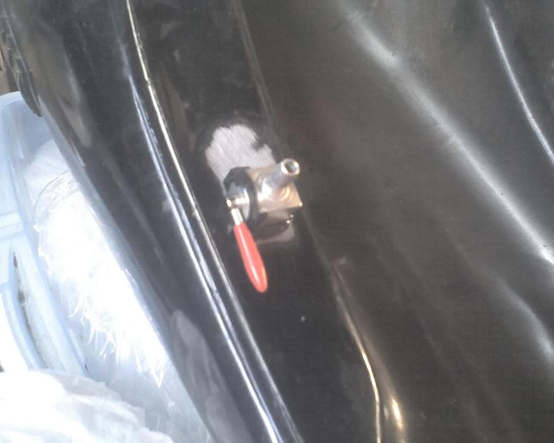
Riding it is held back by two things. Primarily, the tank is currently off. I need to fit a return line to it and I don’t want to do that without a valve for it. I will visit my neighborhood shop (which has been very helpful in this and other projects) tomorrow and get an appropriate valve and fit it to the tank. I will also get him the part number for the K&N filters I want to try.

Of some concern about fuel, I saw somewhere where someone burned up a fuel pump because the stock petcock in their application could not supply fuel quickly enough to cool the pump. It flowed enough to supply the engine, but not enough volume to cool the pump. I’m not going to worry about that before it’s a problem, but I will be looking for it.

The other thing holding back a ride is that in the time the bike has been sitting unused, the front brake appears to have gone completely dry. There is some misting on the caliper, but it doesn’t appear that all the brake fluid leaked out, but nonetheless, there is none in the reservoir. Granted, for a test ride, filling and bleeding the brake system will be fine, but the actual problem needs to be addressed…

As I sit here typing on my laptop, which sitting a board across the arms of a camp chair within easy reach of Buzz, I’m filled with a great sense of satisfaction. I made it go!

Let’s not add up the dollars just yet….

It RUNS!


9/25/08 20:05 CDT It ran!

I had to dink with it a bit. I think there was still air in the injector line. Once it settled down, I can get it idle pretty well and it revs quick after an initial hesitation. I am working on that.

However, VERY elated that after all these months of delays that Buzz is running on MegaSquirt!

Fuel Pump 101


Ok, I figured out what happened to the fuel pump. I broke it, but not the way I thought in last post.

I now believe that the pump was not leaking when I first tested it. To minimize fuel spillage and to keep from having to remove the entire assembly to tape the pressure gauge threads, I used the ubiquitous ViceGrip pliers to pinch off a line in the spot where I would presumed the majority of drain-back fuel would have come from. After I powered the pump up, pressure did not come up and I noticed the ViceGrips still in place and powered it down again. I noticed the wetness from the leak when I was removing the pliers. With the pliers off, pressure came up as it should, but with fuel pouring from the pump.

I removed the pump today and have found the culprit. It’s a feature, not a bug. Pinching off the line where I did meant that the pump pushed full pressure without the benefit of the regulator to bleed off the excess. There is an over pressure relief valve on the pump and that is apparently where the fuel is leaking out.

It looks like a ball held down with a spring. I probed at it and now in operation it just seeps a little fuel, but it still leaks. I’m guessing that there is some debris in there keeping the it from fully reseating.

To get the project going while I have the time off work, I have decided to plug the over pressure valve port. I won’t be pinching off a line like that again and I will be shopping for a replacement pump because the over pressure valve really should be there, but for now I need to get this thing running!

I used brake cleaner, followed by acetone to clean and degrease the port. I mixed up some JB Qwik, the fast setting version of JB Weld and dolloped a bit in the port. I used a thin rod to stir and push the epoxy into the port and applied more, repeating until I was pretty sure there were no more bubbles in it. As I write this, it is sitting upright waiting to cure. JB Qwik is set in just a few minutes, but it says four hours to cure. It will be a loooong four hours.

One thing I will do during those hours is cranking the engine watching the coil leads to see where I need to connect the tach input. Hopefully. I may even try to run it on starter fluid enough to verify that MegaSquirt sees it spin.

Denied!

So very close…

First all the good…

I got everything (and I mean everything) except the TACH input wired today. There is some question as to exactly what exactly constitutes the negative side of the coil. I will just have to try to crank it and see what I can see and hopefully find a suitable place to connect. Otherwise, I may have to hack out some other place to pick up a tach signal.

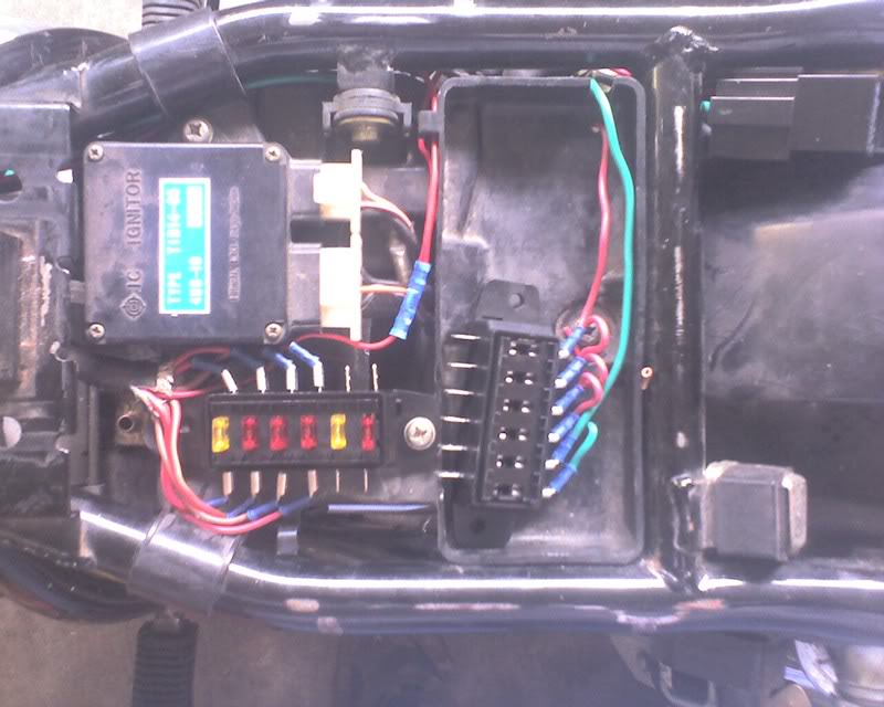
I did not plan on replacing the stock fuse panel, but when I was attaching the main relay to the ignition fuse, the fuse clip broke. I started to fix that one, but another broke. Due to an ordering snafu when I was gathering parts for this project, I happened to already have a 2nd fuse block, so it was just a quick decision to replace it and an extra 30 minutes or so of crimping.

I mounted an LED to the fast idle output. Without realizing it, I bought a blinking LED, which is probably better anyway. As long as it’s blinking, run the bike at fast idle. When the light goes out, take fast idle off.

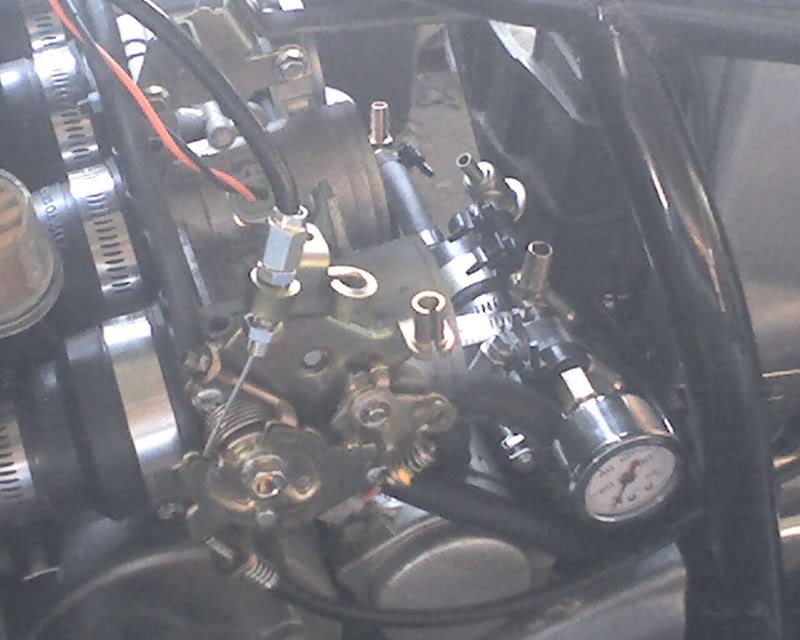
The big thing that was waiting was all the fuel system plumbing. 10 hose clamps, 2 tees, 1 adapter and 1 pressure gauge later, it was ready to pressure test. I connected a fuel supply and powered up the fuel pump. It took a little bit to prime the pump, but suddenly, it zipped up to 42 PSI. A bit of fuel leaked from the gauge fitting, but I forgot to tape the fitting first. I pulled it, taped it and fit it back. No leak.

Well, not from there. Turns out, it was leaking from another spot that I didn’t see in the first run up. Leaking profusely from the plastic fitting around the power leads. It didn’t leak when I bench tested it a few months ago. I presume the pump was damaged in the intervening time, probably from bouncing around in the tool box. :/

Without the fuel pump leak, I would have been attempting to start the engine tonight. Bummer. Between that and the squadron of mosquitos, I called it for the night.

Tomorrow, I will pull the fuel pump and see if anything can be done with it. If not, I will have to find another before I can continue.

Slow but steady progress…


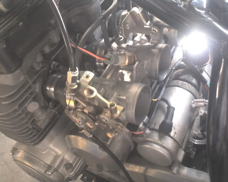
Today, I got a longer throttle cable. It was originally for a Suzuki somethin’ or another, but most important, it’s enough longer to work!

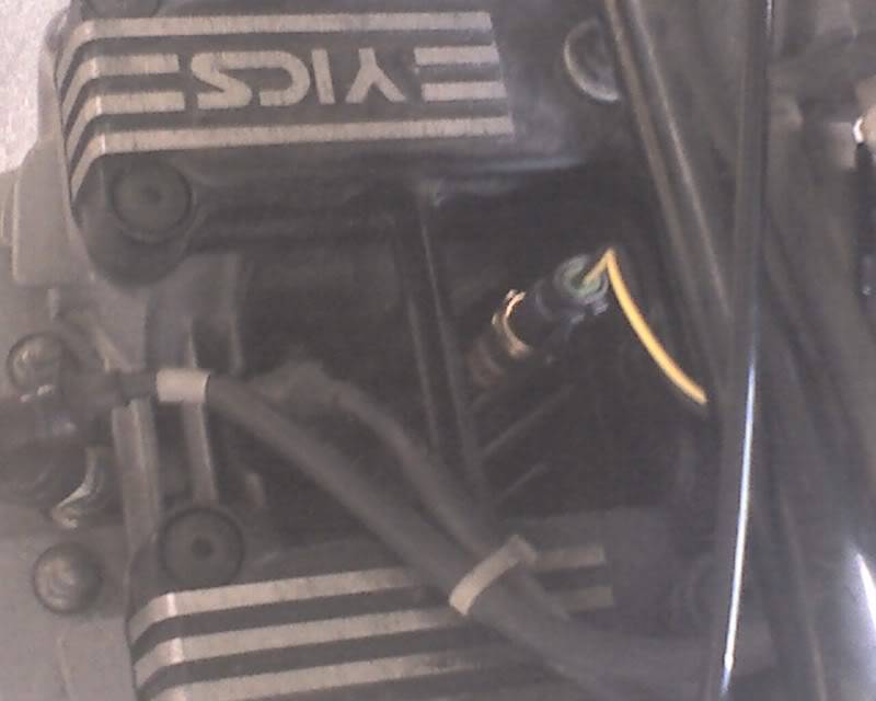
From the same picture, you can see where I drilled a hole to mount the IAT sensor on the throttle bodies and secured it with JB Weld. It will be sensing temperature of the airstream between the filter and the butterfly on cylinder two. :)

The CLT sensor is trickier. I have it jammed between fins in the top of the cylinder head, between the plug on cylinder two and the timing chain and secured with ubiquitous JB Weld.

I made the brace for the throttle bodies and routed some wiring and the MAP sensor hose. I am having trouble arranging the pressure side of the fuel system. I think I can fix the routing problem with a 90 degree fitting, and I need some kind of fitting for a pressure gauge I want to include. To the hardware store!

This evening, I upgraded the embedded code in my MS-II to 2.886 and started filling out the parameters. We’ll see if it will start on it….

A pretty good day’s work…


I had a fairly productive day after killing a lot of the morning looking for suitable wire. I could find red and black everywhere, but you need more colors to help keep things straight when you’re hooking up a dozen different things. I ended up with black, red, green, yellow, blue and white.

The throttle bodies are mounted again, though they will need to come back off for a bit tomorrow. The wiring harness for the throttle body and the temperature sensors have connectors. The fuel pump is mounted and has a connector. The connector for the controller is wired, though I need to mark the function of some of the wires that use the same colors.

I go shopping in the morning and assuming tomorrow afternoon progresses as well as today, I may be trying to start Buzz by Wednesday or so, though with no oxygen sensor and using the stock ignition.

Tomorrow’s to-do list includes a little shopping, most importantly for a longer throttle cable. I only need about 4 inches more. The stock cable works as long as you don’t have to steer, especially to the right. Actually, it would work quite well for lefthand doughnuts.

I have decided to use the stock choke lever to operate the fast idle cam. I will hook the fast idle solenoid output to a light on the dash. When the light is on, work the lever. When the light goes out, return it.

More as it develops!

Time to Play!!

I have a week off work so I should have a week of quality wrench time with minimal interruption!

There has been little active progress with Buzz since my last update. I have also acquired a VW trike which has taken a good bit of my tinkering time. Of course, I am always looking at the trike and making plans to MegaSquirt it, too. LOTS of potential there. In fact, if I were so determined, I’m certain I could have it running well before Buzz, with only one semi-major purchase.

In any case, my plan is to see how close I can get to having Buzz running by the end of the week.

There is a long list of things to do. Some of it is parts fab and I imagine those things will take the biggest part of the time.

I need to get together a mounting plate for all the electrics. There will be relays, fuses, connectors, the controller itself and the EDIS module. I have ideas in my head; I’ll have to see if they will translate to reality.

Since I’m putting all this in the space where the airbox was, I also need a fender to keep dirt and perhaps more critically, water, out of the area. I would like to keep it as light as possible. Maybe I can use aluminum flashing. I once made a replacement fender for an RV using flashing and pop rivets, sealed with silicone.

Another kinda major fab I must do is the return line to the fuel tank. I think I will try to leave the stock petcock as is and add a fitting, perhaps sealed with epoxy. If I can satisfactorily make it safe to do so, I will braze the fitting in place instead. It will be much more secure.

I need to put an oxygen sensor in the exhaust. For the short term, I will use a narrow band sensor for cost reasons, but I hope to upgrade it. You can do so much more tuning if you know the exact O2 reading, as opposed to the go/no-go reading from the narrow band device. The wideband sensor could open the possibilities for running Buzz on alternate fuels, even propane. :)

The final big fab isn’t so much a big fab as a complex one. I can even skip it for a while if needed, but I need an ignition trigger wheel. I have in mind a pretty simple way to make one using my drill press and hand tools. It needs to be precise but not so precise that I can’t pull it off manually.

All I need after that is a longer throttle cable and to put all the stuff on the bike.

Well, for good results, the bike needs valves adjusted and oil changed and I’m sure the battery has gone bad in all these months of sitting idle.

For today, it looks like I might need to have plenty of MAPP for my torch.

Fuel pump mocked up and working

I won’t continue to bore you with the mundane delays in this project. I’m sure they do not make me unique! :)

In any case, I had a few minutes yesterday to connect the fuel pump on the bench, or the top of the trashcan, if the truth be known. I had a plastic can of what is technically old gas, but it was fine for this mockup. I had to prime the line by forcing some fuel into the intake, but once it was there, it worked great.

A long time burning question was how much current the pump would pull with the system under pressure. Looks like 3.46 amps, about 1/3 of what I feared, so I can go on with my electrical life.

Fuel pump work


As expected, using an internal fuel pump externally presented a little issue.

As can be seen (blurrily, sorry) here, there is an inlet at that would be the bottom of the pump. This inlet was originally connected to a screen and surrounded by what was basically steel wool, forming a simple fuel cell. I connected and clamped a length of 3/8″ fuel line with an inline filter to this inlet. It’s not a very long nipple, so I expected to need some way to stabilize the connection for installation, but for bench testing, this was ok. I connected the outlet to the regulator with 5/16″ fuel injection line and the relief port of the regulator to a length of 1/4″ line. The free ends of the 3/8″ and 1/4″ were plunked in a gas can. The plan was, apply power and if it works, it will build pressure, trip the regulator and all the relief will flow back into the can in a closed circuit. It took a bit of priming to get it lifting fuel out of the can, which won’t be an issue on the bike, and looking only at the two ends, the fuel flowed as expected!

All was not rosy, however… in this view, you can see a smaller hole, in the upper righthand area of the endpiece. This hole spews gasoline under pressure when the pump is running. In the in-tank installation, this would have simply flowed back into the sump in the tank where the pump was suspended. I suspect that it’s part of the cooling scheme for the pump motor.

I analyzed the circuit and I have decided that there is probably adequate flow through the pump and regulator and back to the tank to cool the pump internally, or at least I’m willing to try it. With the pump not submerged in fuel as well, it may well run warm. Gotta get it hooked up first to see….

I elected to raid the plumbing shelves again. I found a 1-1/2″ to 3/4″ copper reducer that fit nicely to the end of the pump. I drilled a hole in the side of the 3/4″ end and fitted a couple inches of 3/8″ tubing there and brazed it in place. To keep the overall length down, I avoided using a short length of pipe and a cap to plug the end and instead cut a flat disk of copper from another fitting and brazed it to the 3/4″ end. I also cut the larger diameter end shorter. The adapter fits pretty close to the pump intake. The assembly is attached to the pump with a neoprene sleeve and hose clamps, originally intended to joining cast iron sewer pipe :)

Tonight, I hope to connect the whole thing and let it circulate for a while, checking the temperature of the pump and perhaps of the fuel as well. I want to pick up a fuel pressure gauge, but they tend to be either too large, too low pressure range or both. Guess I’ll have to order one…