One can find plenty of derision online concerning the Arduino IDE. Shrug. Maybe I am not sophisticated enough to care that much about the occasional issue. I do have two main gripes about it. Once you start a compile, there does not appear to be a way to abort it. This comes up often for me because I will make some change that needs to be compiled and uploaded to test, then while the compiler is still building, I will see some other error that I need to correct. The best I can so is unplug the board so that at least the upload will fail. That brings up the other issue, although this may not be specifically an Arduino IDE issue so much as a general hardware issue. All of these devices that I am working with connect to the PC via USB. Sometimes, all the unplugging, replugging, pressing the reset button on the boards, etc, will cause the USB subsystem to kinda get lost. I don’t know if it’s the IDE, the UART chip drivers on the boards or what. Related to that, those UART chip drivers don’t always get along with USB 3.0. Since I do 99% of this work on a laptop that has two available USB jack, I use a USB hub that happens to have two USB 2.0 jacks and one USB 3.0. My current project requires me to develope on three interconnected devices at the same time and one of the available jacks on my laptop is occupied with my USB headset, it can be pretty easy to forget and plug something into the USB 3.0 jack on the hub. I realized this is a problem once the cards kind of stop responding. Thus far, it takes a reboot to restore trustworthy function.
So, besides all that, I find the Arduino IDE itself is just fine, at least until you have to communicate with something more complex, like a TFT display. The data being fed to the working display is generally not the issue; it’s getting the thing working in the first place. A problem that I had early on, though I have largely solved it by now, is that ESP-NOW is implemented a little differently in the supplied libraries for the ESP32 and the ESP8266. My intent was/is to put tiny ESP8266 boards in the remote devices and a more capable device equiped with a screen and some buttons driving a menu system as the controller. The example code provided for the ESP32 family is much closer to a good starting point for my project than the examples provided for the ESP8266.
The library names are slightly different, which is itself easy to fix, once you know the right library names to use. Trickier to solve, however, is that a very important data structure is slightly different and at least one constant name is different (ERR_OK vs ESP_OK). Luckily the incredibly helpful Programming Electronics Academy published a video on exactly this subject, using the example code from the ESP32 family and modifying it to run on an ESP8266, although I was not aware of it until I was a couple of days into trying to find and solve the problem myself.
Armed with this info and some time to figure out exactly what I needed to accomplish, I got two devices working and the devices can send and receive data from each other.
Next, the ControlBox device needed to be able to send it’s data only on demand. I replaced the delay loop with a few different implementations of detecting a button press. It’s roll as the ControlBox will require it to accept some kind of switch change to send that Activator the go command. Eventually, it will be able to respond to either a local switch or a remote ESP-NOW device sending the appropriate request.
With the button sorted out, I started the activator conversion. The current analog system, where we just throw voltage at a door lock motor to trip the activator. This fairly elegant and thus far very reliable. However, the lock motor is physically large and even though used only briefly, it is pretty power hungry as well, requiring an also physically large industrial timer relay to protect it. Converting this activation device to a servo will recover the space that will be better utilized by a battery in the new design and the servo will arguably require less power.
Getting a connected servo doing *something* itself fairly easy, but getting it to do precisely what I want it to is much more difficult.
As I never stop putting “ESP NOW” in the YouTube search, I stumbled across another way to do this stuff.
The video that introduced me to Visuino makes no mention of it in the title, but as I watched it, there was this visual IDE being used. It was almost mentioned in passing, but in very nearly 8 or 9 minutes real time, an ESP32 board and an ESP8266 board were set up by dragging virtual components onto the screen, interconnecting them with on-screen wires and a few settings in the components. One has a temperature/humidity sensor and the other a small OLED display. The display on one shows the temperature and humity data from the sensor on the other.
It is pretty easy to argue against using such packages from a strictly code efficiency point of view. Visuino produces code that is essentially impossible for the inexperienced programmer to follow and the code sizes produced would not be unfairly called monstrous. My most complex sketch to date (spoliler: I am using Visuino) is nearly 300K and doesn’t only slightly more than the 3K Arduino IDE code that preceded it. These ESP controllers have megabytes of RAM and FLASH to work with, so it is kind of a non-issue.
All is not perfectly rosey, but with an hour or so of judicious tinkering, I had a working receiver, receiving the data sent by my “old” Arduino code. Getting it to activate the servo based on receiving that data turned out to be tougher to figure out, though largely becase I struggled with the kind of object oriented approach after so much time in procedural methods.
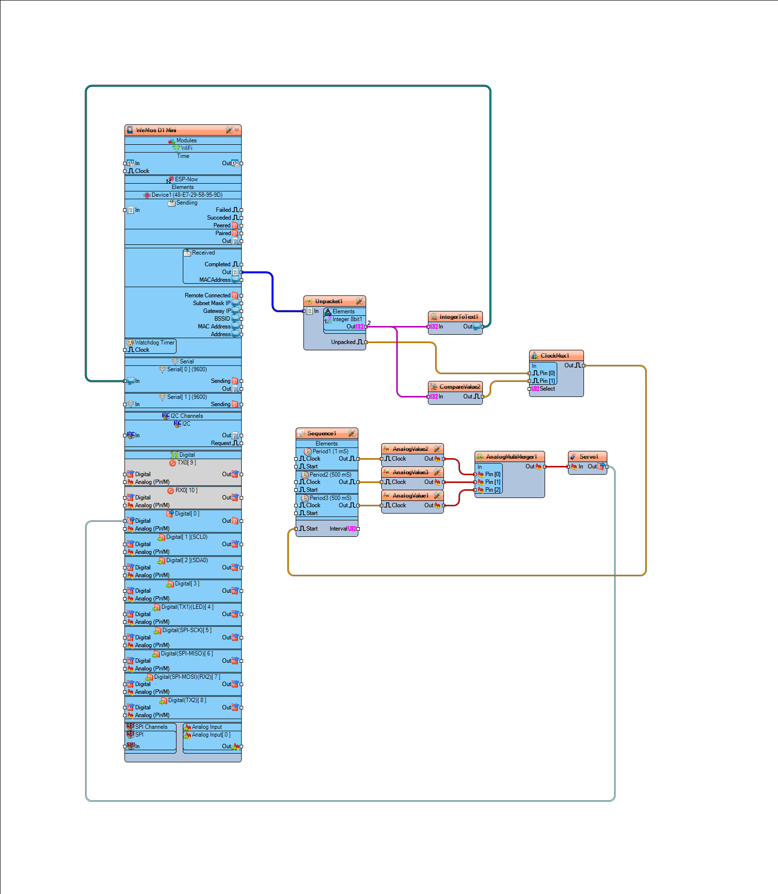
The the knowledge gained by the receiver project, it was much easier to reconfigure the sender into Visuino and then to add a button to the sender.
Just this morning, I succeeded with the quick and dirty version of what will one day be deployed in the field, a Trigger device that will initiate the action, a ControlBox to intervene and/or modify before it sends the command on to the Activator.
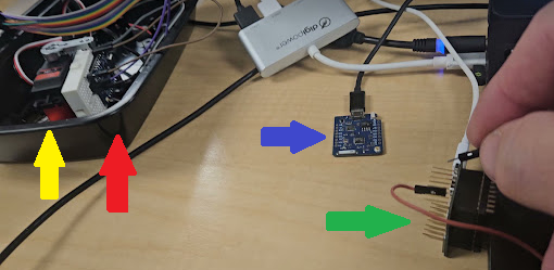
The Trigger (green arrow) responds to a switch closure and sends a byte of data to the ControlBox (blue arrow) which resends it to the Activator (red arrow) which does a quick 90 degree cycle of the servo (yellow arrow).
For this quick demo, I am using all ESP8266 boards, specifically the Wemos D1 Mini Pro, which supplied with an external antenna connector. Since at least one of these devices will be inside a closed steel box, the external antenna is likely to be a requirement.
The 8266 boards are perfectly appropriate for the two far ends of the system and probably fine for the ControlBox as well, however I would like to put something with a screen and menu buttons on the ControlBox so that features can be selected in a friendly way. The list of features are still a work in progress list, but includes things such as being able to detect and add new devices and the ability to trigger multiple activators, maybe with a timing sequence between them. There quite a few controllers available that already have a screen and buttons and other features ready to go, taking away some of that development time required to make the interconnections between those peripherals and Visuino makes using those peripherals easier. Maybe.
One problem I face with Visuino is that, while there are a lot a supported devices, I already have several devices that would be appropriate to try, but they are not implicitely supported in Visuino. The Arduino IDE provides a pretty easy way to add support for new boards by providing a list of URLs where the supporting device descriptions can be pretty much transparently downloaded. There is a similar list viewable in Visuino, but thus far, I have not found a way to add to it.