A select few interested members of the shooting public saw the gadget yesterday. Reception was generally positive and a couple of suggestions will make it into future versions.
I was already going to remake this one to solve a couple of serious issues before it gets used in a real match in a couple of days, most importantly getting the pull rod away from the lock motor. I spent a good chunk of my Sunday doing just that. Behold the improved whickerbill:
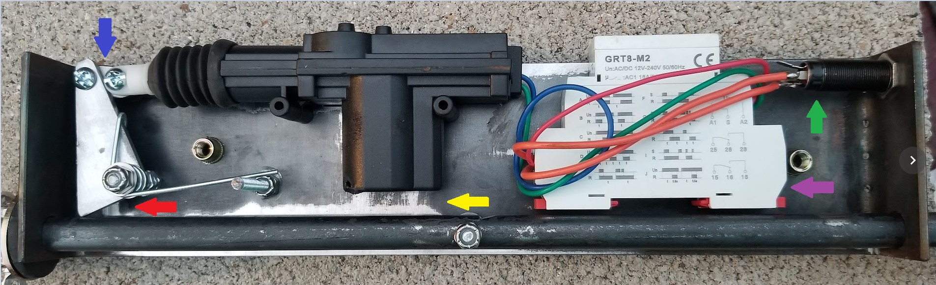
Starting from the yellow arrow at the bottom center, there is now gobs of space between the pull rod and the lock motor. Incidentally, the case of the lock motor was actually breached by all the activations in show and tell yesterday. No internal damage was done. I will seal up that hole to keep dust and particularly shop metal shavings out of the very magnetic motor.
Proceeding clockwise, the red arrow points to the new longer but simpler sear. Rearranging things has let me avoid the relief cut that was in the back of the previous sear. The arrow more directly points to what is probably not an issue, but this is a more intense angle. I think I didn’t account for exactly how far I moved the rod when I moved the sear pivot. The sear pivot could really be moved another 1/4″ closer to the rod. It still works perfectly, but this is an area to keep an eye on and I will correct this in the next version.
Continuing clockwise, the blue arrow points to the new articulated link between the sear and the lock motor. I envisioned this in the original design, but just by dumb luck, the previous layout let me skip this link. The new layout requires it, plus it removes some binding strain from this point. This particular link was hand made, but there are some commercial options that I could leverage to save the time and effort of fabricating my own.
Next Vanna is pointing with the green arrow at the input jack, a heavy duty 1/4″ jack intended for speakers. This is not an actual Switchcraft Z15J (those things are rated for 15A!) but I do not expect my little motors and relays to tax it. The purpose, of course, is to make deployment easier. To that end, I also have some 50 foot speaker cables with 1/4″ plugs on either end.
Finally, the purple arrow is pointing to the timer relay. It was kinda halfass bolted down in a weird way on the rush-to-show previous box, but with the pull rod scooted over, there is room to more properly mount it using 3M VHB tape, which means I hope I don’t need to remove it anytime soon.
All this movement still fits nicely inside my 2×4 rectangular tubing, which I derusted with a Scotchbrite belt on the 2×72 grinder, but failed to take a picture of. Soon.
Speaking of fitting in the tubing, I used a seamstress measuring tape to measure the as-built length of the old chassis, from the top edge of one end, across the bottom to the top edge of the other end. Since this chassis is 5/8″ too long, I subtracted 5/8″ from this measurement and cut my new chassis to 14-7/8″ long with the newly secured Vevor shear.
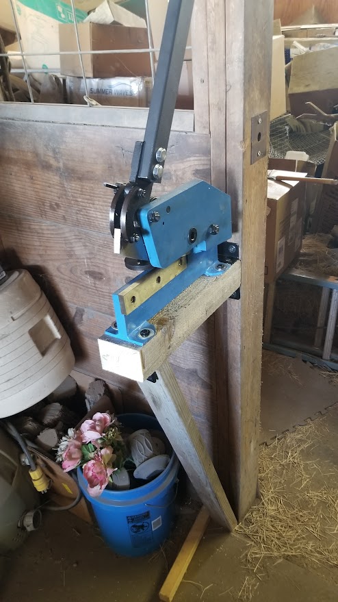
This shear is not even the biggest one they make and it is still kind of a monster. It chewed up my workbench top when I used it to trim a 3″x1/8″ flat by securing it in my bench vise. My first task this morning was to find this thing a place where it could live without destroying everything around it in use. I will one day figure out where in the workshop I can put it, but for now, it is mounted to a beam in the barn!
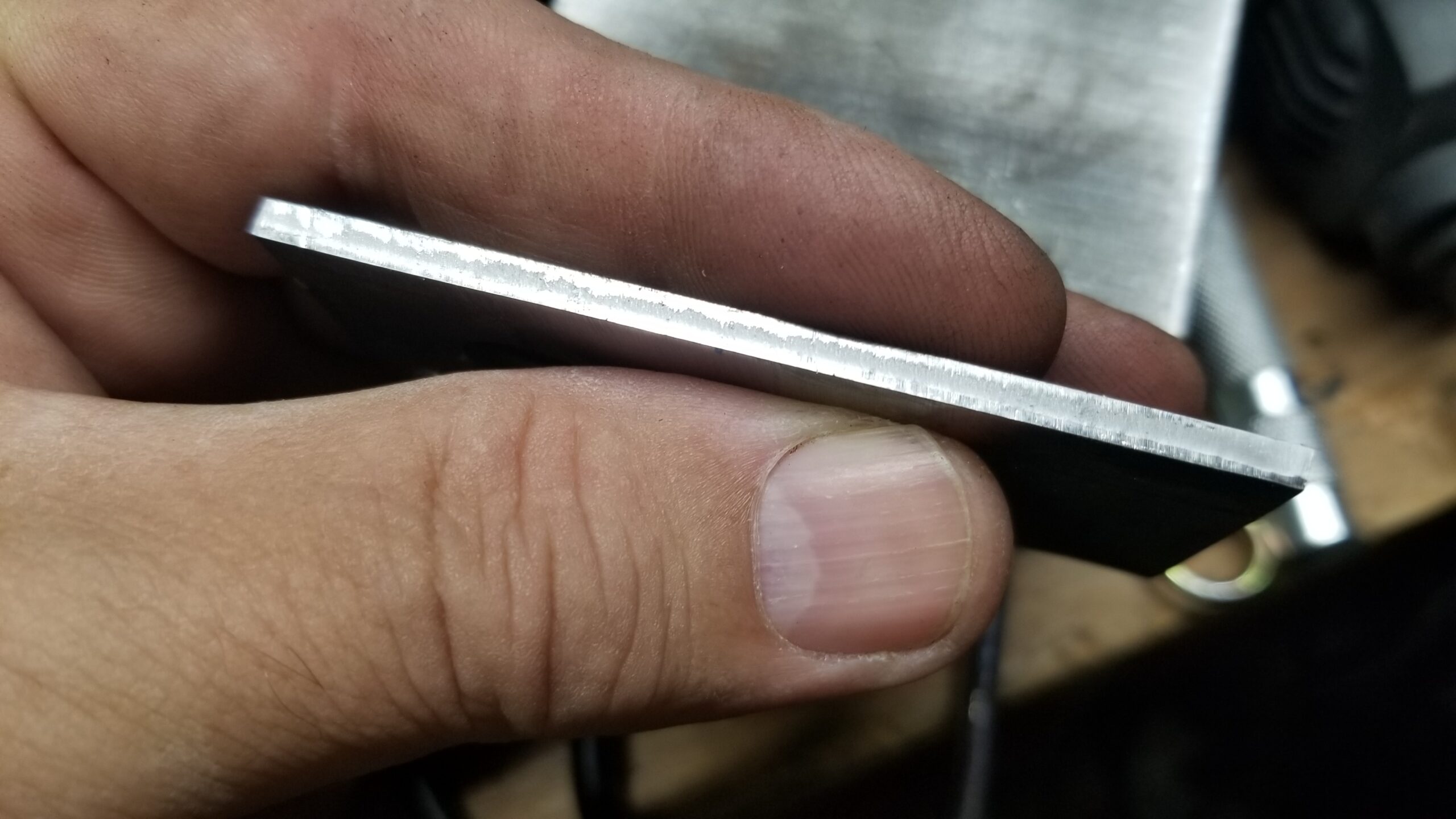
It does an outstanding job on this 1/8″ steel material, though I find that I do need to haul down on the handle with both arms for the longer cuts. That is more testament to one titanium shoulder and one iffy shoulder than anything about the shear itself. However, the shear does produce an excellent edge finish:
Thinner material or shorter cuts are just about trivial. The new sear was made in four cuts with the shear and minimal grinding.
Anyway, once I had the chassis blank cut to length, I measured the inside height of the ends of the old unit, marked that distance from teh ends on the new chassic and drilled holes to assist with bending. I fired up the acetylene torch, heated the drilled area and bent the ends. Everything went quite well.
I guess I didn’t account for the stretch on the outside of the bend when I measured and substracted 5/8″ to shorten the chassis. The new chassis ended up 12-1/2″ long, only 1/8″ shorter than the old one. I was aiming for exactly 12″ long.
The math kinda works. 1/8″ thick material in a 90 degree bend would intuitively stretch out 1/4″. I have two bends and my actual chassis is two times 1/4″ too long. I should have subtracted 5/8″ for the basic length to shorten and another 1/2″ since I was going to add two bends, so my flat blank should have been 14-3/8″ long to be 12″ finished length. We will see if that works out on the next one.