More on the demise of the fuel pump…


Tonight, I pulled the fuel pump out and verified that it would not turn under power and that I could not turn the impeller through the intake port with small sharp tool. I shook it firmly and got small chunks of hard black stuff out of it. With nothing left to lose, I disassembled the pump and found that about 1/3 of the vanes on the impeller were broken off. I pulled the impeller off the motor shaft and washed the bits and pieces out of the pump. I reassembled it (it still amazes me how often I use my anvil in motorcycle work. I used it to make some muffler brackets for Toni’s trike Tuesday night) and reinstalled it, with a filter this time. I also put the valves on the feed and return lines. I fired up the pump and even using a funnel to try to prime it, it would spin but not flow any fuel. I suspect that, while the impeller is badly damaged, it could probably still move fuel. Most likely, the check valve or the body of the pump is clogged with impeller vane bones or perhaps the original debris that destroyed the pump.

I have found several suitable pumps on eBay. Just waiting on the first auction to end :)

I looked into connecting the Honda tilt switch, but it will need a little bit of electronics to work. The tilt switch is open in the normal upright position and “closes” to 23K ohms when tilted. A single transistor and a resistor or two is all that will be needed to connect it.

In the mean time, I’ll be updating the wiring diagrams and impatiently awaiting the new pump.

When Debris Attacks!


I had a few minutes at lunch to troubleshoot the fuel pump issue. I unplugged the fuel pump and put the meter on the harness. Key on, no juice. I pulled the seat off and checked the fuse. The 10A I’d installed while I was in the parking lot down the street was still in place and not blown. I checked the hot side of it and found no juice there, either. I pulled the relay from it’s socket and the battery side of it had no juice. I traced that down and found an inline fuse holder I’d forgotten was there! The 10A fuse in it was blown.

I replaced that one, put a 5A back in the fuel pump fuse holder and verified that I had power to the connector. I turned the key off, plugged in the connector, turned the key on and SNAP! The 5A blew with considerable alacrity.

The coil on the motor reads a pretty normal 1.5 ohms, so my second theory that some debris has jammed the impeller seems likely. Stall current would be about 8A.

I have looked around… A fuel pump from a local bike salvage yard (which moved across town, much closer to me now!) is still a bit high. The one model he has several of and thus charges the least for is still $150. I can get them all day on eBay for half or less of that, but I can’t just walk into eBay and pick one up….

Before I purchase one, I will pull the pump out and see if I am lucky enough for the debris to be lodged in the back of the pump where it can be removed or flushed backward or something before replacing it..

In related news, it occurs to me that I may be able to use these throttle bodies for a while longer by lowering the fuel pressure a bit, delivering less fuel, thus perhaps get a leaner minimum mixture. As it stands, at idle the injectors are opening for what is just about as short a period as possible and it’s delivering too much fuel. The regulator I have is the hard set unit that came with my salvage fuel pump. It appears to be set to about 43 psi, which is pretty much normal. I ordered an adjustable regulator which will run 0 – 100 psi. I think I am going to try about 35 or so to start with.

While I’m doing all this fuel system work, I think I will wire in that tilt disconnect switch that I’d forgotten about… :) And since I forgot about the other inline fuse holder between the battery and the relay, I will update the wiring diagram, too.

Happy New Year!

Got a bit done on Buzz today, enough to get in a short ride. Very short.

I built a fuel feed and return thingy that bolts in place of the stock petcock. I neglected, however, to photograph it before I installed it. With luck, we’ll never see it again. It is quite simply a 5/16″ tap for feed and an elbow with a 1/4″ hose barb for return. It’s actually a single part found on the shelf at AutoZone that I cut. I cut a piece of 1/8″ plate into the proper shape, drilled two 1/4″ holes to mount it. The OD of the tubing is .370 and I had a drill bit that was .373, so I drilled two holes for the tubing. I put those two too close together, however and I had to angle them away from each other to allow for clearance to put hoses on the tubes. I brazed the tubing in, wire brushed the whole thing, cut a gasket and bolted it up. Voila!

This is an intentionally simple design with no valves. I will procure a suitable feed valve and locate my existing return valve and install them soon. Besides the safety issue, it’s tough to have to drain the tank each time it’s removed, so the valves will definitely go on sooner rather than later.

I had previously drilled a hole in the tank for fuel return. I got a flanged bolt, put a gasket on it and used a piece of wire to pull it through the inside of the tank. I put a washer and nut on the outside and applied LocTite. Hopefully, that’s the last of that, too. :)

After that, it was just a matter of putting the tank back on (and rerouting hoses), buttoning up the wiring and putting the seat on.

The front tire needed air and I felt obligated to lube the chain.

The ride down the road was a LOT more fun than the push home… :)

He ran pretty good, actually. I went down my street a couple of blocks, jumped over a block and was headed back toward the main street when Buzz suddenly bogged down and died. He restarted easily, so I figured I just didn’t have enough gas in the tank. I went back to the house and put in about a gallon. My plan was to take him to the car wash, knock some dust off and come back. I decided that if I had troubles, I didn’t want to be on the main road, so I went to a parallel side street and headed for the carwash. When I went over the hump crossing the next street, he died again. This time he didn’t restart.

I pushed him up in a nearby parking lot where there was some light and had a look. I noticed that the fuel pressure wasn’t coming up and I didn’t hear the pump running. I pulled the seat off and found that the fuel pump fuse was blown. I didn’t have a spare 5A, but I did have a spare 10A. I put that in and it didn’t blow, but the pump didn’t run, either. I pushed him home from there. It was only two blocks. :)

I suspect something pinched. It’s too dark to troubleshoot now. I’ll take a look tomorrow.

Smaller throttle bodies enroute

I just won the auction (on opening bid, no less) for a pair of throttle bodies supposedly from a 2008 Kawasaki KFX450R. Now, from what I can find, the KFX450R is a 500cc single, so it would seem unusual to have two throttle bodies, but then Kawasaki seems to have figured out a thing or two. Who am I to judge?

In short, this should be essentially half of the throttle body assembly from the 636. Rather than having to modify what I have, this is ready to go. I will need to fabricate an intake of some sort, but I have a couple of ideas in mind.

In the mean time, I’m still going to see if I can get a ride out of Buzz on New Years Day. That seems a great way to start the year….

EDIS problem (probably) revealed


There have been a few developments since my last update. I guess I’ll cram them all in one post.

I acquired a small oscilloscope. The jury is still slightly out as to whether it’s appropriate to the application, but so far, so good…

There are some limitations to the instrument. The LCD display is not particularly high resolution, so sometimes it’s hard to see the whole story at once. Likewise, there no external trigger input, so the missing pulse nature of the trigger wheel signal is difficult to sync. One has to adjust the sweep rate low enough and manage to capture an entire revolution with the memory function to analyze the finer points and the LCD resolution limits how much you can see at that level.

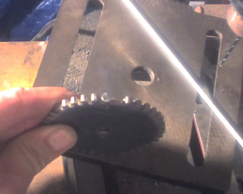
Even so, I was able to see a few things. First, the slightest eccentricity in the trigger wheel mounting is very easy to detect and could indeed be a contributing factor to my EDIS ignition problems. The VR sensor input ranged from 5V p-p down to 0.5V p-p. It’s difficult with the resolution of the display to configure the scope to show both ranges. That alone could affect the EDIS module enough to cause some problems.

Working on a related theory, I set the sweep rate very slow and watched the average amplitude of the VR sensor signal. I arbitrarily decided that low RPM was “normal”. As the RPM went up, the amplitude went up to about 5V, then began tapering off, fairly quickly, to “normal” levels. Since the engine would not rev beyond about 5500 RPM, I am supposing that the stock VR sensor may not have the frequency response needed for this application.

Putting a little math to it, with the one pulse per rev stock trigger, the signal at redline would be about 9500 Hz, or 9.5KHz. With the 36-1 trigger wheel, the signal would be more like 332KHz to 342KHz, depending on how you count it. Keeping in mind that there are radio signals at lower frequencies than that, it’s not surprising that maybe the sensor is not up to the task.

It is under this working theory that I decided to, at least temporarily, return the ignition to Yamaha stock. This means I lose my cute purple wires and those “wrath of Thor” lightning bolt sparks, but it could return me to fighting a single front war.

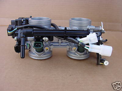
It turns out that it may be worth it, for now I can rev close enough to redline to cause the involuntary retraction of certain parts of my anatomy, and I’m not even riding at the time. There is some detectable miss in the rhythm, especially noticeable at low RPM. I may be suffering the famous Yamaha weak ignition problems, so I will still be searching for a long term solution, perhaps for Dyna coils or maybe driving the coils directly from MegaSquirt, maybe even with big enough drivers to run the EDIS coil. For now, however, perhaps I can march on with fueling issues and determine if I can even operate Buzz on these (quite likely too large) throttle bodies. Down that road are a few possibilities, from cutting my throttle body assembly in half and fabricating a manifold, up to and including restoring Buzz to stock and putting MegaSquirt on something else, probably the VW trike. My wife would like to see me get that thing on the road regardless. :)

I also shoehorned in an oil and filter change, which was probably overdue even when I parked Buzz last May.

Today, before I posted this update, I was explaining the issues to a friend when it suddenly occurred to me that the EDIS module itself may have a rev limiting “feature”. This could make sense because my module and coils came off a Tempo or Escort or some similarly pedestrian vehicle, RPM-wise. Web research, including in MSEFI forums, indicates that the jury is still out. Several people describe similar rev limitations, generally around 6000RPM, but some testing has shown 8000-9000 RPM as a limit.

I’m wondering if the VR sensor could *still* be the issue. Once one exceeds the sensor’s ratings, the module gets bad or no info about the crankshaft position and speed, so it stops firing. The engine RPM drops, the signal gets usable again and there it goes. Consequently, the Ford sensor may not work much better. Furthermore, the limit may indeed be a feature of the EDIS module itself, and that may explain why others *not* using Yamaha sensors on their EDIS modules are having similar problems.

One possible solution may be an optical sensor that may not would not be so frequency dependent. I will keep looking, but for now, I really want to get on with turning the fuel and maybe getting Buzz on the road, so it’s stock sparks for me.

All this, and I still haven’t properly investigated the throttle-failing-to-close-completely issue…

Let There Be Light!


Well, the headlight issue was indeed a simple problem.

When I removed the stock ignition coils, I neglected to secure two ground wires that had been held by one of the ignition coil bolts.

One little bolt and the lights are back on! 8)

Now I just need to fix everything else. I’m looking for the ground wire that will fix the throttle body issue… Wish me luck.

One Step Forward, Two Steps Back


Ok, maybe it’s not that bad. One step forward, 1.273 steps back…

As suggested by a XJ-lister with MegaSquirt experience, I set about reinstalling the butterflies for the subthrottles, the intent being to set them to restrict the air intake. My theory, verified by his experience, seems to indicate that my throttle bodies are probably way too big for this engine. The butterflies restricting the overall air flow into the engine may serve to widen the throttle range a bit. I fear the only real option will be to change them out for smaller unit or perhaps build a manifold to let me use only two of them. Much remains to be discovered, but I need to start somewhere.

I removed the air filters and was able to reinstall two of the butterflies without difficulty. Of course, the first one I tried on the “dark” side of the bike (the side away from the lighting in my workspace) crossthreaded and twisted in half in the removal attempt. After warming the area with some rather colorful language, I removed the throttle bodies, drilled out the broken screw, installed the two remaining butterflies, LockTite’d all of them and finally secured the assembly at the recommended 9 degrees from open.

I reinstalled the throttle bodies and started the bike up, only to find that now the throttle doesn’t close against the stop. I can gently force it against the stop, but it springs back open, reving high the whole time. The only thing that comes to mind is that maybe when I put thread lock on the screws, a drop fell in on one of the throttle butterflies, dried there and is now holding them open. I suspect it will be #3 because it seems like it’s always #3. :roll:

Well, with the bike trying to idle at it’s maximum attainable RPM of about 3800, the air restriction does not appear to have been too much. The advance is still crazy up there and it surges like it’s hitting a rev limiter, but at this point, I have done no adjustments to the ECU, just added the subthrottle butterflies back into the intake tract. That, and broken it such that the throttle is cracked open pretty much permanently.

Just this moment, I’m far too frustrated to safely pull the throttle bodies back out to troubleshoot the stuck open issue, so I will call it a night.

Juice and Fuel


As suggested by an XJ lister, I checked over my meter and there is indeed something flaky about it. I turned it on and with nothing connected, it showed 38V. One sound tap and it settled down. I found that I could spin the selector switch a few times and make it screw up a bit, but after running through the ranges, it settled down. This meter has bounced around in tool boxes, floorboards, saddle bags and my driveway for about 10 years now, so I think it’s due a little crotchitiness, especially since it’s almost always sitting on the 20V range :)

In any case, with it settled down and reliably measuring 12v and 5v from a known good PC power supply and 9V from a fresh 9v battery and 15.5 from my laptop power supply, I now feel I can trust it.

So, I started measuring voltages on Buzz.

Before I started, the battery was at 12.6V. I turned on the key and saw it drop immediately to 12.4V then slowly ‘drain’ down to 12.1V after 3 minutes of just sitting there with the key on. At that point, running lights, instrument lights and the ECU would be the only current draw.

While cranking, it dropped to 10.5V. As is the current state of the project, it was hard to get him started and running, but once going and warm enough to idle and run, I had enough hands and eyes to watch the meter. At idle, battery voltage is about 12.8V, at 2000RPM steady, it’s 14.1. As I recall, those seem to be reasonable figures to indicate that the alternator is at least working.

The headlight is still quite dim, but it does fluctuate with reving. It still never gets above what I would subjectively call about 40% brilliance. More on that subject later.

The battery itself is still slightly suspect, because the cranking voltage drops pretty deep, so I will probably replace it anyway. I have not checked the spark while cold cranking the engine lately. The low cranking voltage is probably contributing to the trouble starting.

With the battery voltage question shelved for the moment, I set about trying to extract a little better running condition. Another one of those little things bothering my subconscious about the fuel system is the tendency of the fuel filter to run “dry” when the fuel pump is running. The fuel pressure seemed to be ok, so I put it out of my mind. Yesterday, I was browsing some of the MS forums for stuff about power loss at certain RPMs. At least one post suggested that fuel starvation could be a factor. I rev Buzz up and, as usual, it sounds like the engine hits a rev limiter at about 3200 RPM, but this time, I watched the fuel pressure gauge during the event. It bounced down from the usual steady 42psi to about 35, jumping roughly in time with the stutter. Hmmmm.

The return from the regulator for my temporary fuel supply is a clear hose. It’s been handy because I can see flow in it and that gives me an operational check at a glance. Well, an extended bonk against the pseudo rev limiter revealed another symptom that simply hadn’t occurred to me and would not have been easily detected without the clear hose. Bubbles. Lots of bubbles in the return line, but only when the engine is stuttering at 3200 RPM. Hmmmm, ok.

I bypassed the fuel filter and tried again. No bubbles in the return line and while it still sounds like it’s hitting a rev limiter, now it does it at about 4300 RPM and there is no fuel pressure gauge bounce. There is still much tuning to do, but I now feel that fuel starvation is probably no longer a factor.

A tweaked around with the fueling settings in MegaTune, but didn’t make any huge progress. By that time, it was getting chilly enough outside that my fingers, especially on my mouse hand, were getting cold, so I wimped out and packed up and went inside.

The brain, however, doesn’t stop and I began trying to figure out why the lights would be dim when the voltage should be high enough for bright lights. Something to check came to mind this morning….

Alert readers following the blog will recall that when I needed to tap an ignition switch controlled voltage, clips on the stock fuse box were pretty much falling apart in my hand. I had a spare DelCity fuse block, so I replaced the stock fuse block. What occurred to me this morning is that I crimped those connections and perhaps I have a bad enough crimp to limit the current available to the headlight.

Current Events


No, no election coverage here… we’re talking amps!

I’m surprised that I didn’t remember to do this until last night, namely measure the current draw of various components of the system.

For each measurement below, I first started and ran Buzz until warmed up, mostly so he’d idle without fiddling. Then I shut him off, pulled the fuse feeding the measured equipment and bridged the fuse connection with my ammeter probes. I started the engine and noted the values at idle, while reving and while holding the speed steady at what is currently the highest at which he’ll run smoothly, about 3200 RPM.

As expected from the start, the fuel pump may be the largest draw, coming in at 3.7 to 3.8A. This is also a fairly steady draw, since so long as the engine is running, the fuel pump is on.

The next big draw is the ignition system, coming in at 700mA at idle and 1.6A at speed. I suspect this value will climb at higher RPMs due to the nature of an ignition system. It’s essentially a PWM signal in which the pulse width stays about the same, but since the frequency increases, the apparent percentage gets larger, thus the current draw will go up.

Everything else is almost trivial, but may not be exactly accurate because the low range fuse on my ammeter is apparently blown.

The fuel injector rails draw 70mA each at all speeds. This will probably go up a little as RPMs get higher for similar reasons that the ignition system will draw more, but proportionally, it will still be a low value. Even at 100% duty cycle, each injector would draw a little less than 1A and with this small an engine, 100% duty cycle would pretty much be a hydrolocking degree of flooding.

The ECU itself appeared to draw about 30mA, but that seems low according to the documentation. I would expect it more like 100-200mA. The final measured value is the FIDLE output. One day, I will have a solenoid there, but for now it’s just an LED. The 10A range on my meter would probably not show it, but since the engine was warm, it wasn’t lit anyway so no reading.

All this measuring of current draw made me take note that the headlight was pretty dim while the engine was running. I checked the battery voltage and it was 11.58V, unchanging when either revving the engine or shutting it off. That is extremely unusual. With no charging system, I would expect the voltage to raise a bit when shut off, the load having been removed. If the charging system were working properly, it should raise when reving. I didn’t even see it change with my external charger connected. Hmmmmm

In any case, Buzz is to the point where I can begin tuning the engine in other RPM ranges, though I now also need to get this electrical issue resolved. No juice, no go.

Trigger Wheel Dentistry


Short version: It worked.

Long version: I varied the plan slightly, based partly on not having the right size drill bit. I didn’t have a small bit to use for plan A, so I used a 1/8″ bit and, since I happen to have a gob of them, a 1/8″ x 3/8″ steel rivet.

I centerpunched the appropriate spot and drilled a 1/8″ hole about 3/16″ deep in the edge of the wheel. I drilled another 1/8″ hole to intersect the first one. I inserted the rivet to the right depth, which was scant less than bottomed out. I used a center punch to stake the rivet in place. I cranked up the torch and filled the space in with brazing rod through the intersecting hole. Easier to do than to describe, I think.

After that, a little grinding, filing and wire brushing and it’s got another decent tooth.

I used what I’m sure will turn out to be temporary spacers and bolted the wheel to the crank. It took a couple of times to get it adjusted close enough to start, once it was going, Buzz had what was actually a pretty ok idle. All four pipes hot!

The signal is a solid 1.8V, so I gained quite a bit of signal power. I suspect the timing is still a little off because I can’t get him to rev over about 3500 RPM and by then the advance needle in MegaTune is swinging wildly. Sounds kinda like he hits a rev limiter that recovers kinda slow. The RPM is nowhere near the rev limiter settings.

Most importantly, I now seem to have reliable ignition, so next time I get to work on it, I think I will button up the ECU and EDIS module into their permanently attached locations.

As for the trigger wheel, what’s left is to solidify the connection to the crank. The wheel sits just about perfectly on two nylon spacers that I got at the hardware store. At this point, the plan is to get a dowel pin long enough to secure both spacers to the crank, use the timing light to get the wheel within the timing adjuster range of dead on, then use another smaller dowel or roll pin to secure the trigger wheel to the spacers. The roll ping will reside under the fender washer under the bolt that holds it all to the crank.

Let the tuning begin!

Sluggy Blogs All The Subjects