Before the swarm of Asian Tiger Mosquitos chased me in the house, I got several more important bits done, leaving plenty to do tomorrow during the day while the vampiric minions from the East are busy dying from the Yard Guard.
While I will also be dropping the body off for upholstery, I intend to try to get enough done to attempt crank the engine. Admitedly, that’s pretty ambitious, butcha gotta have goals…
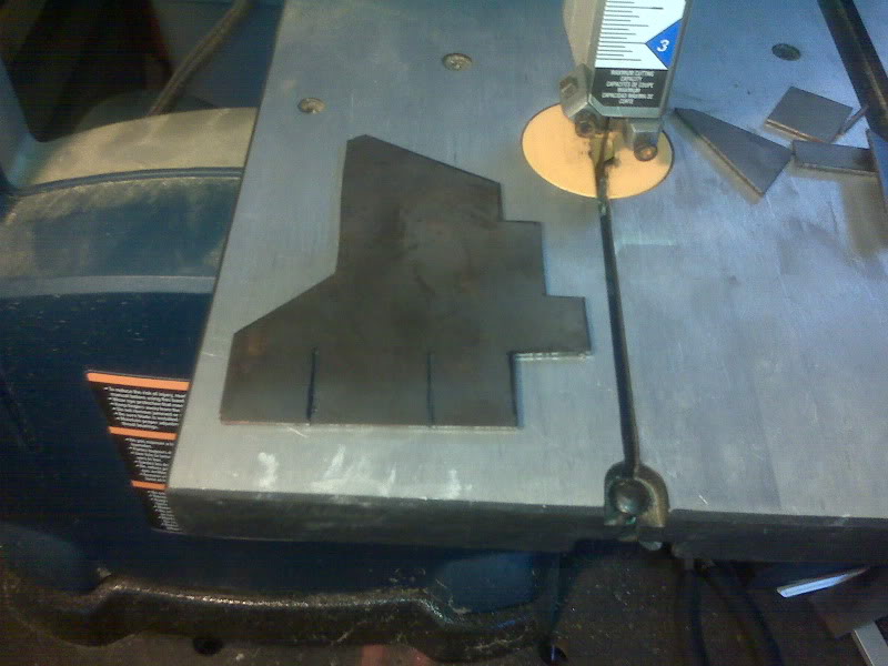
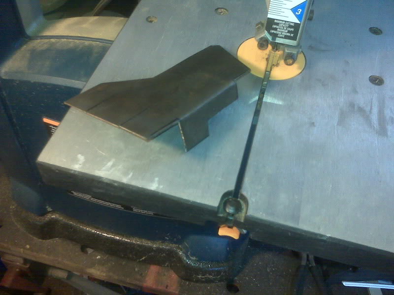
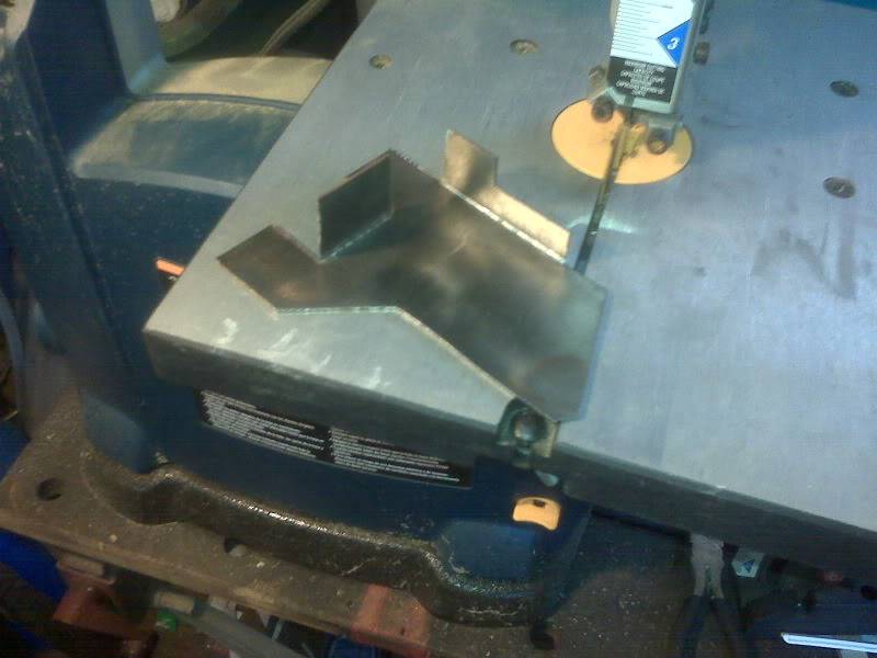
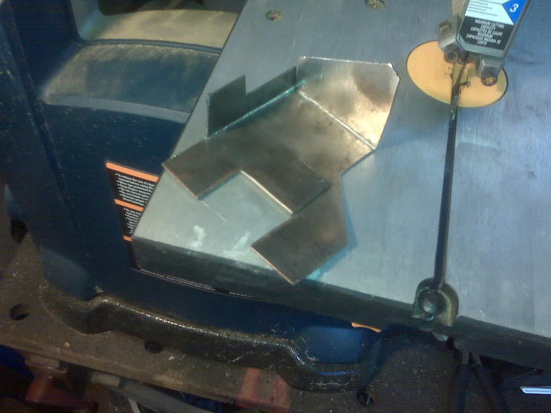
Mechanically, the biggest thing will be finishing off the fuel tank, which is putting the pump in it, putting the filler on top and mounting it. I also need to cut and mount the plate that all the relays and such will be mounting to.
After that, it’s just wiring. A lot of wiring, but just wiring.
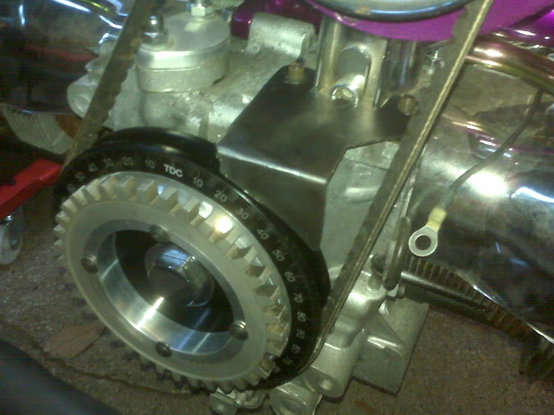
The throttle body has connectors for the TPS and IAT sensors, as well as the IAC motor and two injectors.
Speaking of injectors, I still have not been able to identify the EX650 specific injectors well enough to discover their flow rates, so I substituted two injectors from the throttle bodies I removed from Buzz. Their flow rate is known to be 245 cc/min. Guessing at a couple other values and plugging them into the Req_Fuel calculator, these injectors should provide a reasonably long idle pulsewidth. This was a big issue with Buzz, where a 538cc engine was trying to idle when supplied with fuel from four of these injectors. This 1600cc engine with only two of them should be a better match. The nose of the 245cc injectors is slightly shorter that the stock ones, but I don’t expect it to be a problem.
But back to the wiring…
I have a waterproof box to put the ECU in. Hopefully it won’t run hot in there. All the relays and fuses will be on a plate or board just in front of the engine.


