It appears that the transaxle on Sponge Bob may be one of the semi-rare 1967-68 models. They are semi rare because a) they were only made for two years, b) most of them are still in serviceable cars and/or c) they are very desirable for trike building.
The reason for the narrow year range is that in 1967, they changed the electrical systems on Beetles to 12V and in 1969, they went to the IRS transaxle instead of the swingaxle. The change to 12V is important to the transaxle because they also changed the diameter of the flywheel from 180mm to 200mm. To fit a 12V flywheel that will mate properly with a 12V starter, a 6V transaxle needs some clearance ground away on the inside of the bell housing. That was done with Puff, and while I’m sure there is plenty of material, I’d rather have something that fits without modification.
There is really no such thing as a new VW transaxle, although some companies make high dollar aftermarket units that are all new, like Mendeola and Albins. These are mostly “call for pricing” priced, though I have seen a Weddle IRS transaxle priced at $7000.
Generally, freshly rebuilt swingaxles seem to run about $500, sometimes less.
I found a VW salvage yard that had a 12V swingaxle for $200. There is basically no warranty, though I’m sure if it was DOA, they would make it good.
So, way back in October of 2011, I picked it up. They were attending a swapmeet that was much closer to home than their place, and they were kind enough to bring it with them.
Then life got complicated. My mother-in-law became ill and eventually passed on. Thanksgiving and Christmas came and went. Within that whirlwind of activity, we moved, or technically, began to move, to a house in the country. It is a tremendous place on about 7.5 acres that has a nice house, a pond, a barn and workshop, horse pasture, several outbuildings.
Did you catch that? A workshop! An indoor workshop, with power and lights and a freakin’ door. That closes.

Sadly, with Sponge Bob stuck in gear, I still have to work on it at the old place, under a carport, dodging mosquitoes.
Fast forward to March 2012. A close friend died suddenly. His birthday was May 5, so at his widow’s request, we planned a memorial ride on his birthday. I was going to have Sponge Bob ready for her to ride with me in comfort, so as the date approached, I tore into preparing the transaxle I had picked up in October.
The brakes and such on Sponge Bob have always performed pretty well, but I couldn’t get that monster hub nut broken loose. It goes on at 245 ft/lbs torque, so it’s not infeasible to need 300-400 to break it loose.
My alternative was to get new wheel cylinders and hardware to go with the new brake shoes, seals and bearings I already head and just put all new stuff on the backing plate on the replacement. It came with hubs in reasonably good shape.

I ended up working out of town most of the week leading up to the ride, so when I got back into town Friday afternoon, I tore into it with the plan to get it on the road before Saturday morning, if I had to work all night. I came pretty close to that. I cleaned up and headed home (which is about a 45 minute drive now) about 3AM.
There was, however, no joy in Mudville.
One of the last steps before starting the engine was was to adjust the hydraulic clutch. I have done this enough times to make short work of it. I can get in the ballpark just by hauling on the release lever and taking up the slack in the cylinder adjuster. It usually needs just a little adjusting from there. Adjusting is easy; with the transaxle in gear, I push the clutch in with my left hand and kinda bounce the trike forward or back. If it bounces against the gears, tighten the clutch a bit and repeat until the trike rolls freely with the clutch in and bounces against the gears when the clutch is out. It kept bouncing. Having had the clutch too tight a couple times in the past and having it jump off the cross arm at full extension, I did a sanity check by slipping it into neutral then pushing on it. Oops, it bounced when it should have rolled.
Long story short [too late] this transaxle is stuck in a gear, too. First gear, by the other evidence. It doesn’t matter what position the gear selector is in, it’s in first. Well, except if you put it in 4th position; that locks the transaxle.
I borrowed a trike (which is kinda like borrowing someone’s kidney only with more blood) and the ride proceeded with dignity and grace, though with great fatigue on my part.
Fed up with used parts, I have elected to get a rebuilt transaxle (with a warranty) from The Bug Stop. I dropped off the original stuck-in-forth unit at lunch today. I will remove the replacement stuck-in-first unit tonight for delivery tomorrow. They will mix and match my parts and their transaxle as appropriate and credit me for two cores, producing a ready to install transaxle for a reasonable price expected to be around $400 total.
With any luck, they will have it ready by this Friday and I will have Sponge Bob on the road by Saturday afternoon.
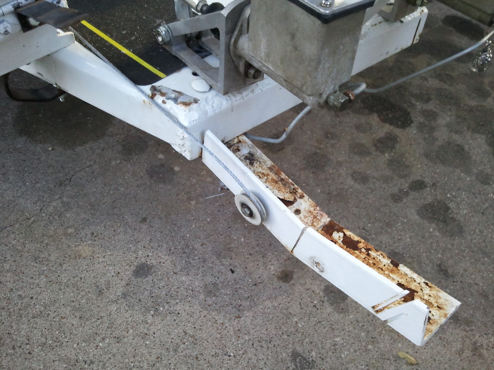
Between now and then, I will attempt to permanently repair a very old chassis and body problem on the trike, too.