All posts by Sluggy

Puff Shifter

Since Gabby took the white trike to work tonight, I reworked the shifter on Puff.

The first thing I did was shop for a ratchet U-joint with the least play in it. I chose a spark plug socket with a built in U-joint. here it is compared to the previous joint for the transaxle end.

First, I cut the end off the other joint. It is part of an adjuster, so it is the proper size for the coupler and includes a set screw dimple. I also cut the end of the socket off so that when the end is bottomed into it, it is the minimum length. This should make the entire assembly shorter with less side loading when shifting.

I clamped it up…

And welded it together.

I then cold forged the the end of the tube to fit the drive end of the socket and welded that. There is the completed joint.

I test fit the shaft to get an idea where I would have to move the shifter.

Next came the tougher bit. I repositioned the Super Shifter so that the new shaft can be used with it’s single U-joint. First, I cut off my ever-so-carefully placed shifter mount, then cut the rear bracket shorter, while hand fitting the shifter. Once I was “happy” with the placement, I used a jack to hold it at the right height, a drill bit under the box to hold it at the correct angle to the ground and a C-clamp to clamp it to the shaft for the proper angle to the transaxle.

Sorry about the odd angle. I was trying to eliminate shadows and reflections off the chrome box. I ended up leaning so far over that it’s like I held the camera upside down.

Anyway, made those two welds and I really hope the fiberglass body still matches up correctly.

All that remained was to cut the shaft to length and to grind the end down to fit in the coupler.

I have used a drill bit as a temporary pin, but here’s the completed shifter.

Compare the angle with the previous attempt:

This layout works MUCH better. It works so well that I foresee speedshifts.

A Thousand Points of Light

Ok, maybe not a thousand…

Gabby was running late enough that she didn’t take the white trike to work on Tuesday night, so I put the handlebar switch on and wired it up.

Because the new headlight has a halogen bulb and I wanted to put the auxiliary light on with the high beam, I used a relay to power the headlights rather than smoke the old motorcycle switch. Fused power is on the common (30) and one side of the coil (85), low beam on the normally closed (87a) and high beam/auxiliary on the normally open (87). The high beam position of the switch grounds the other side of the relay coil (86)

I also connected the horn button and the turn signals. I did not, however, test the signals and managed to reverse them! Left switch signals for a right turn and vice versa. It’s taped and tied down well enough that I didn’t want to tear it open to swap them. I ran out of time, but I should have it again Thursday night and I’ll swap them back to normal then.

A Little Light Drama

No light is dramatic at night.

After the BTW meeting, Gabby rode the white thing to work, with me and Sponge Bob in escort. There were no (known) problems. When she got off work that night, she had no main headlight and the smaller “high beam” was dim and/or flickering. I did some quick field testing and decided that the bulb must have gone, as new stuff is sometimes likely to do. We used some wire ties and spit to get the smaller light to stay on and rode on home.

This evening, I chased down the troubles, and there were indeed two independent failures. Some NASA engineer is getting fired for this…

First, the main headlight, the new one. I’m the engineer getting canned for that one. I used a self-soldering heat shrink type of connector and maybe I didn’t heat it enough or something. It didn’t bond well and with it sinking current for two halogen filaments simultaneously, it heated up and came unsoldered. Ground open, no light.

The smaller high beam thing had a similar problem, but this one wasn’t my fault. This light was operated by a small rocker switch mounted on a bracket on the left mirror bracket. Neither the wire nor the solder point on the rocker switch was adequate to power that light. One of the wires had come unsoldered from a switch terminal. The wire can’t be any bigger than 20ga and the switch is probably good for 1A. For the short term, I connected the lead from the light directly to power in it’s harness.

So, the white thing’s headlights are semi-permanently wired to the keyswitch.

I have begun refurbishing the handle bar switches (and throttle) from a Suzuki something or other than the previous owner of Puff threw in. They fit one inch bars. I wire brushed all the paint and corrosion off the left one and painted it. I decoded the wiring and I will be ready to install it one evening this week. It will cover hi/lo, turn and horn. The right hand switch has a run/stop switch and a start button. Just this moment, those functions are covered elsewhere, but I’ll still be interested in using them.

Tinker gave me a couple of screws for the cooling tins. I applied them both the cylinder tins. The 1-2 cylinder tin didn’t have any screws at all. Neither did the doghouse.

Then I noticed a bigger problem. The righthand fuel tank bracket either lost it’s bolt or never had one. There is a welded-on 3/8″ nut on the frame bracket it bolts to and it had a lot of rust inside.

Anyway, I found 5/16″ bolt and nut, manhandled the full 8 gallon tank into position and bolted it down. Someday, I will replace the 1/4″ x 1″ flat straps with 1″ angle or maybe 1″ square tubing. Either would be way more rigid and better suited to holding up 48 pounds of gasoline.

The As-Yet-Unamed White Trike

I apologize in advance for not taking many pictures of the work on the white trike. We were kinda rushing to get it on the road so Gabby could take it to our BTW local chapter meeting on Sunday.

The white trike was pretty much in ready-to-inspect condition, other than a silent horn.

Friday after work, I made a couple of stops and got some things I would need to put an obnoxiously loud horn on it.

The existing horn did have power to it, but not even a peep would emanate. I ran a wire from the old horn to a relay in the engine compartment. I mounted the horn by the battery and connected it to the battery, through the relay and a fuse. Of course, the positive battery terminal was corroded, making it difficult to connect to and the rubber battery tie down crumbled in my hands, so I went to the ubiquitous Autozone. I replaced the battery terminals, which involved cutting the charging lead from the generator since it’s bolt on the old battery terminal was inaccessible without a time machine. When I went to put a new connector on the charging lead, the corrosion had leached up the line, preventing it from taking solder. I elected to replace the wire, which was a good idea because it turned out to have a splice in it.

All that is fixed up and man, that thing is loud

For following is the very short version because it’s 2:30AM and I am having trouble forming complete.

See, I told you… I am editing this early Sunday evening, and I’m leaving the previous line there because that’s exactly how I wrote it at 2:30AM.

Saturday, we went shopping for parts, most notably a vacuum advance distributor to banish the famous flat spot. We did a little more parts shopping and went home. The inspection of the trike went without issue, then we started into the stuff we’d bought for it.

I forgot to take pictures for most of it…  :/

I did take a picture of the first post-purchase bling to go on, a fuel pump blanking plate.

You might expect most anything *except* a fuel pump blanking plate installation story to include a bit of excitement. pshaw…

The trike runs with an electric fuel pump, and flushed with the relative success of my previous fuel pump blanking plate installation, I was keen to get on with it.

In the back of my mind, I think I noticed that the existing mechanical fuel pump looked kind of new and the previous owner reported that they had installed an electric fuel pump. When I tried to put in my blanking plate, I discovered why.

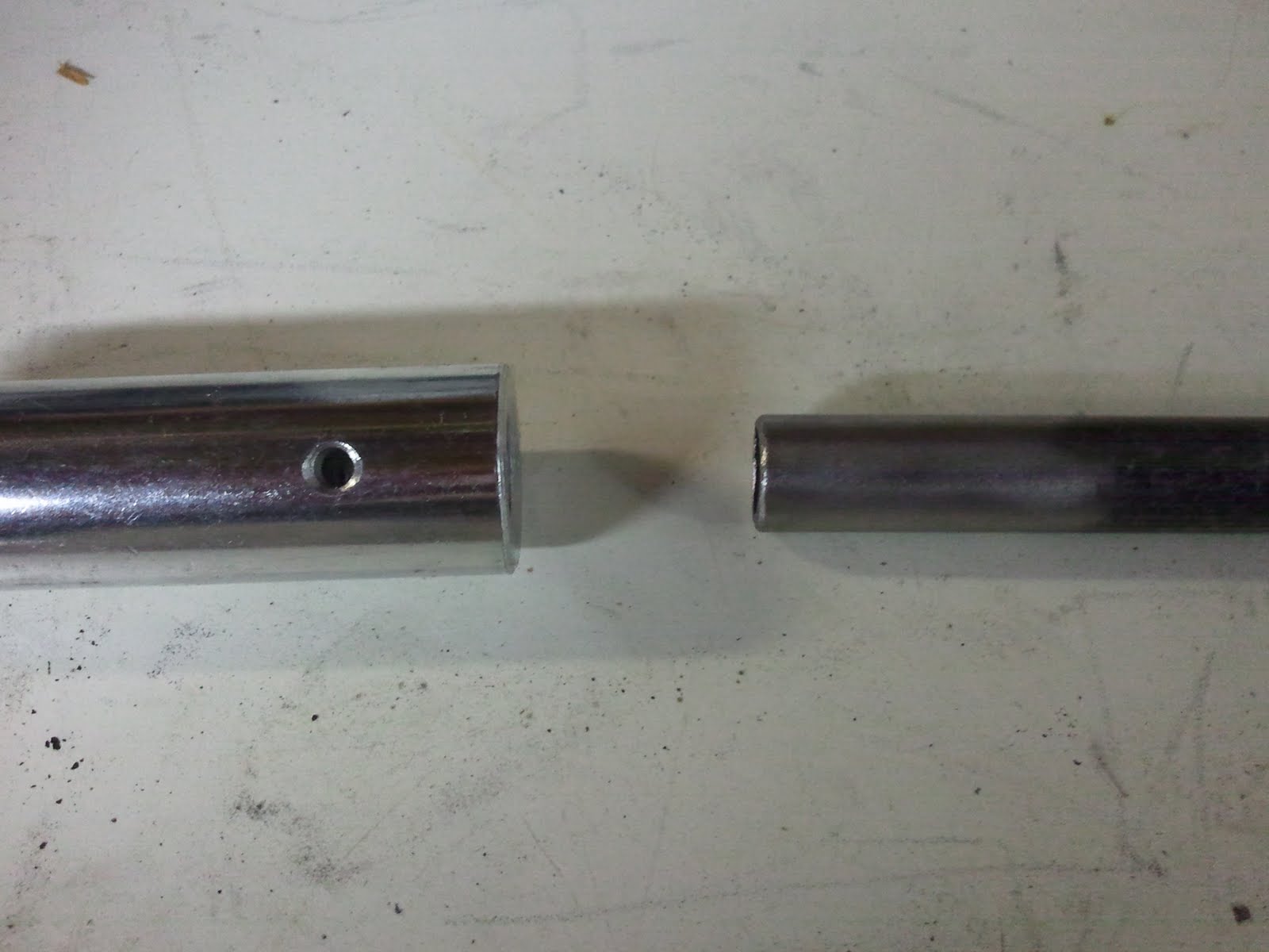
An aircooled VW engine fuel pump is operated by a pushrod that is rides an eccentric on the distributor drive shaft. Older, generator equipped engines use a pushrod that is about 4.5 inches long. Less old (factory) alternator equipped engines used a shorter fuel pump to clear the larger alternator, and thus had a shorter 4 inch pushrod. The smaller pump will work on either engine, so long as you have the shorter push rod. From the various auto parts stores, the smaller pump is just about universally stocked, but ya gotta use that shorter pushrod. This engine had the longer pushrod.

I’m sure the first time the installer cranked the engine, it was either very exciting or all they knew is that the engine still didn’t run.

For my part, it took a lot of pulling and tugging and twisting to get the bent rod out. Then the plastic heat insulator thing was broken. There is a piece of it still firmly attached at the bottom of the hole, though now it is nicely covered with a shiny new blanking plate.

Installed the distributor.

Just setting the basic timing might have gone a long way with the old one, but it runs WAY better now. Incidentally, the old distributor had a Pertronix electronic ignition module in it. I toyed with moving it to the new distributor and I am still interested in doing that, though I want to make sure I can just pull the sensor disk off.

I did *not* install new pulleys because the generator pulley was pretty well stuck and it looks like the crankshaft pulley is there to stay, too, since someone freakin’ welded it on….

 In case you’re wondering, ya don’t do that. And, just in case you somehow think you need to… say, you live in a post apocolyptic desert and maybe large bolts are scarce…. a couple of tacks or stitches would be more than enough to hold the pulley on until the horn sounds… You don’t need a continuous bead.

Sadly, my heroic efforts to remove the pulley before I discovered this little tidbit bent the pulley. I again owe a debt of gratitude to the inventor of the deadblow hammer. May his lead shot ever flow.

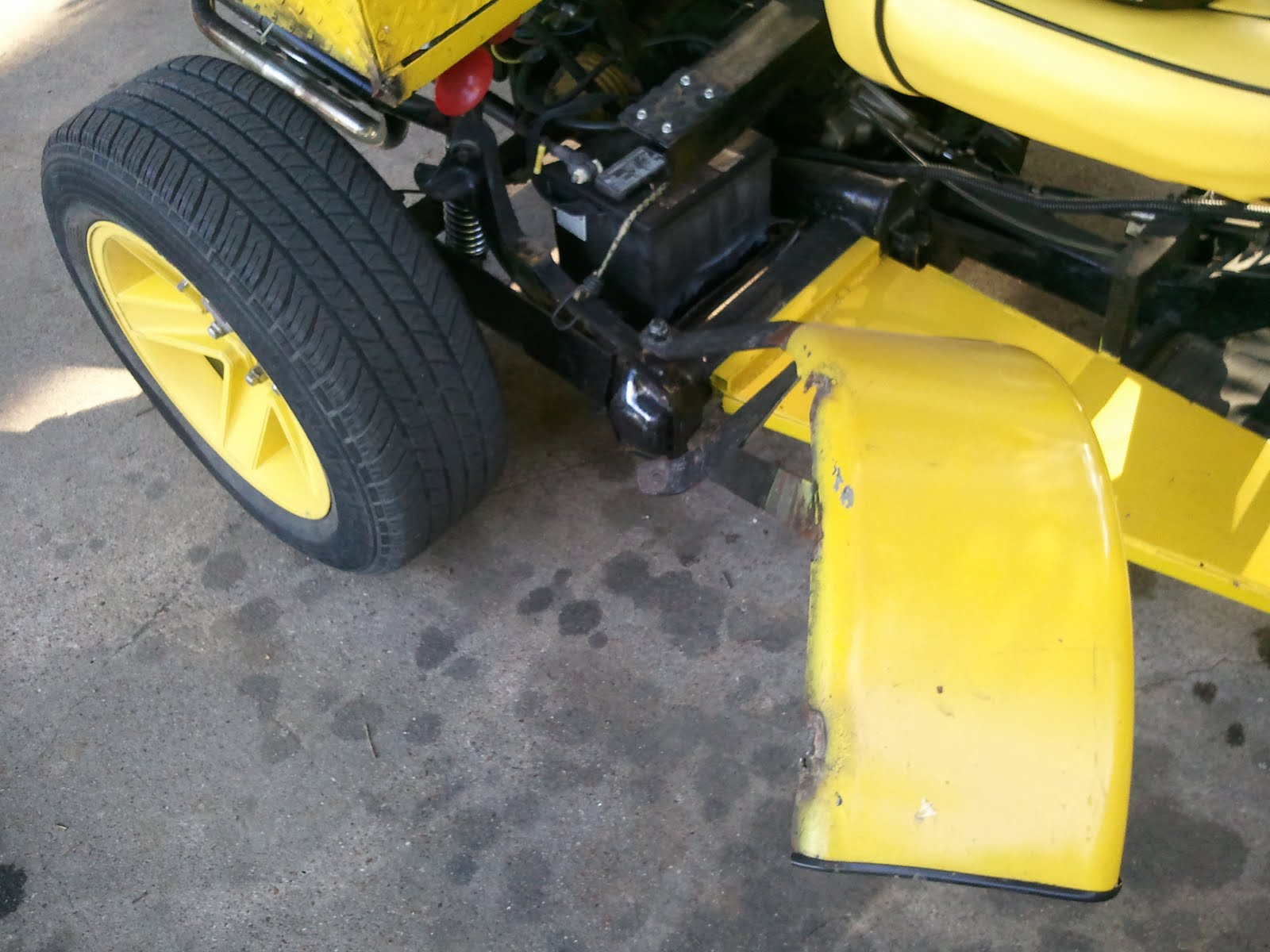
There was a long list of things done to it Saturday evening, such as adjusting the seat, changing out the shifter (one of three steps needed to make it shift nicely), cleaning the air filter (think I saw Cuban Holy pollen in there), quick and dirty painting of the bonked fender, screws and TyWraps to minimize rattling, lots and lots of polishing, cleaning, buffing and namecalling.

After staying up so late Saturday night, we got up early Sunday morning and moved the brake and clutch pedals off the kind of strange pods they were mounted on. Time did not allow me to reroute the foot throttle cable, so the one for the brake is still physically there, but that will go soon.

The trike made it to the meeting without incident and was well received and Gabby took it on to work. I am about to go meet her for the ride home…

Sponge Bob Fender Trauma

As I was leaving work one day this week, I noticed at the right fender on Sponge Bob, which has always been pretty iffy, had come loose again, loose enough to rattle while the engine was warming up. I mentally added securing it, again, to my todo list.

I headed on home. The rattle was noticeable, but I didn’t pay much attention to it until I suddenly heard the fairly specific sound of metal on tire, a clunk, then no more rattling, just as I was traversing a railroad crossing.

I looked down and saw basically this:

Of course, I was moving at the time…

I turned around in a parking lot to got back and retrieve the fender.

It’s a big yellow fender, you’d think it would be easy to see. While I was turning around, a commuter train came through. Even though it took me a little bit to get turned around, I wouldn’t have thought anyone would have time to have stopped and pick it up, even stopping for the train. I couldn’t find it anywhere.

Then, during one of the turns I made, I saw something out of the corner of my eye.

The fender was still attached by one bolt, but had swung around forward and I just couldn’t see it with my helmet on!

I laughed heartily and just held it up by me for the rest of the drive home, which was only about a mile.

Shift linkage

I used 1/2″ weldable tubing to make a shift linkage.

The shifter came with a coupler that I used on that end. I had to take down the diameter of the tubing just a little for it to fit.

There is a roll pin supplied to stake the rod to the coupler. I may decide to use a more easily removable pin for the final assembly.

I used 3/8″ ratchet U-joints for the linkage. On the shifter end, I formed the tubing into a square end to fit inside the U-joint. I ground the face of the socket down to provide more surface area and to remove the chrome plating and welded it in place. On the male ends of the U-joint, I ground the tenon down to approximately cylindrical to fit inside the tubing and welded there.

The joints have a little more play than I had hoped. If they introduce too much play, I will try to tighten them up. If that doesn’t work, I may need to start over with better U-joints.

On the transaxle end, I used a shift rod adjuster but modified it. I hot forged the threaded end into a 3/8″ square to fit into the ratchet U-joint, shown here before welding.

The results look pretty good to me…

Still left to do is a support brace/bearing to stabilize the rod between the shifter and the first U-joint. I think I will use an appropriately sized bronze sleeve attached to a brace attached to the frame, although I have considered using Nylon. I will probably need this brace to be adjustable, so I will probably need to weld a tab to the frame for the brace to bolt to.

The New Checklist

So, not mentioned in the last post was the other reason I haven’t been working on the trike. I figured that whenever I tore into the shifter that I would be honor-bound to do a bunch of other things that would be best done with the trike body removed. I also figured that I would probably find other things that needed doing once I was in there. I was right. So, now I’m committed…

In no particular order:

1. When I put the new footpegs on, I did so without grinding off some old weld flashings and such that were largely unreachable with the body in place. Well, not only must I do that, I also need to repair the handlebar wiring harness. I managed to put the footpeg U-bolts over the wire and tightened them down. That it hasn’t shorted out already is only because the footpegs have not been in use.

2. I had not noticed before that the reservoir on the brake master cylinder was empty. Even more so, I had not noticed that the surface of the master cylinder appears to be wet with brake fluid. I think the reservoir has been bumped too hard and too many times. Besides, it’s not really designed to sit at an angle. I will look into a remote reservoir. I know the adapter for one is very simple.

3. I had a wiring issue that came from all the wires being tied down without any wiggle room. This resulted in at least one connector getting pulled from the back of the fuse panel and with the body in place, there was no reasonable access to properly correct the issue, so I ended up adding a “bypass” wire.

I need to restore the original wiring and maybe more importantly, prevent that from happening again. That may require cutting loose 197 TyWraps, rerouting and/or extending some wires and maybe even adding some bracing to the relay panel to keep it from moving.

4. I need to connectorize the speedometer sensor. It was one of the wires I had to unsplice in order to remove the body.

5. I also broke the (admittedly temporary) master power switch when I failed to notice yet another zarking TyWrap that connected it to the body. I have a really nice keyswitch that is supposed to be used for that, but I have been reluctant to saw the required hole in the fiberglass to install it.

5. Not even *one* of the wire tie pads that I stuck under the fiberglass body stayed. The wiring harness fell everywhere. So, no more self-adhesives or double-sided tape. I am going to epoxy some screws with fender washers attached to use as studs for standard metal wire loom clamps to attach to. I really want this to be the last time I have to address this issue…

6. Though this doesn’t necessarily require that the body be removed, it will be much easier with the body off, and that is to finally get the fenders on the trike. The old fender mounts will need significant modification to fit the new fenders, especially the left one which was itself suddenly modified in a collision untold decades ago.

7. The old fuel tank has had a lot of work done on it and still needs so much work that I might be time and effort ahead to replace it. It has at least one remaining pinhole leak that is currently plugged with an epoxy patch, I have a remote fill spout that will need a suitable fitting on the top of the tank and I have a fuel level sender to install. Rebuilding the tank to account for all these changes seems like a good idea, and might allow me to increase capacity at the same time.

The Long Anticipated Shifter

After months of mundane interruptions, including hair curling heat, I finally tore into the the new shifter for Puff.

Thus far, it appears that the method I devised for transposing one shifter location to the other is working.

First, here is the old shifter before I got started. At this point, I had already removed the shift linkage.

I started by cutting a template and bolting it in place where the shifter would go.

Then I welded a couple of temporary braces between the plate and the frame.

Then I could remove the bolts and cut out the old shifter.

I forgot to cut out the template plate for the parts on the face of the disassembled shifter box. I drew in the shape from measurements, cut out the relief and bolted the shifter box on the check the fit.

At this point, I realized that a) I needed some bolts and b) chances were pretty good that the hardware stores might close early on Labor Day, so I skedattled.

When I returned, I made a plate that would become the new shifter mounting plate.

and bolted the entire assembly together, template, shifter and mounting plate, with my new bolts, seen here from the back.

I measured, cut and fit two braces to attach the mounting plate to the frame…

… and welded them into place.

I removed the shifter box…

Cut off the temporary mounting, reassembled the shifter and this is what it looks like now!

What’s left is to build the linkage. It will basically be a few lengths of 1/2″ tubing connected by U-joints.

The shifter handle is held in place by a split ring. When it’s removed, the body should easily fit over the shifter, then the handle is reinstalled.

After playing with the shifter some, it appears that the reverse lockout may be more trouble than it’s worth. It requires enough effort to engage that it is very difficult to do with one hand *and* apparently you have to press the release to get *out* of reverse as well.


Sponge Wobble

The new tire is nice and sticky, but did not affect the wobble, but that’s ok because now I remember why…

The rear wheels, especially the left one, have a wobble. It’s very subtle, but definitely enough to affect the front end.

My first fear, and probably why I put it out of my mind, is that the axle was bent.

Having suddenly remembered this, I began shopping for axles for the eventual replacement. Turns out there are two lengths of swing axle, so I consulted the oracle (“Tinker” in my local BTW chapter) and he suggested that the axles are VERY hard to bend and that there could be several much easier to fix things wrong instead.

Last night, I pulled the left wheel off and, while I could not find my dial indicator to quantify it, I did not *need* the indicator to see that the aluminum wheel adapter is bent.

Upon further investigation, I see why it’s bent…

The brake drum, in a departure from the usual hub/drum setup for Beetles, has a separate brake drum and wheel hub. Seems that it may be the way the brakes are done on a Type 3. The brake drum is held on the hub by two low profile bolts.

The bolt shown here interferes with the back of the wheel adapter.

Someone tried grinding away some material on the back of the adapter:

…but either they didn’t remove enough or they didn’t remove it soon enough and the adapter plate bent.

These plates depend on one eccentric bolt in order to adapt a hub with four bolt holes to a wheel with five studs.

It occurs to me as I write this that I may be able to reposition the eccentric bolt to a hole adjacent to the low profile bolt head. This may simply bring a different spot into interference.

I will try that with the new adapters, which I am picking up a lunch today, but I may end up just cutting away some material to relieve some clearance on the back of the new adapters.

[update]

I forgot to update this blog until the next entry was already posted. I removed the two low profile bolts, “depending” on the lug bolts to hold the hub in place. The rear wheel wobble is gone. The 30MPH front end wobble is unchanged.