Running on EDIS


Monday fighter practice was canceled due to rain, so I got to play Buzz on Monday afterall…

I elected to use the stock coils on EDIS, at least for the time being. With the stock ignitor module removed, I could not seem to isolate the coils from ground. They are 3 ohm coils, but I kept seeing about 10 ohms to ground. Later analysis of the wiring diagram seems to indicate that there is a relay coil on the common power lead, so this may not be such a bad thing. I will more carefully check it out, for as it stands right now, the kill switch and the kickstand safety interlock are inoperable and I’d rather they weren’t.

So, before I figured all that out, it was a simple enough matter to wire spade lugs to leads and run the leads from the EDIS to the coil pigtails under the tank. I connectorized most of the module wiring. I used a 3 pin connector for the coils and a 2 pin for the connection to MegaSquirt. The stock VR coil is connected by spade lugs; long term, I may do that differently. The module ground is on a ring under the same engine block block as the main ground and is the only wire without some form of quick disconnect.

For power, I needed another main relay power source for the module and coils, but I didn’t want to tear into rewiring the fuse block. What I did in the short term was move the FIDLE power and fuse to the spare from the fuel pump relay and put the EDIS power to the former FIDLE circuit on the main relay, with a 15A fuse. This means that the FIDLE light only lights when the fuel pump relay is energized, when the engine is running or during the pressure-up interval when the ignition key is first turned on. I don’t expect that to be an issue, even if I do manage to get FIDLE working with a proper solenoid. That spare fuel pump tap was intended, however, to power the EGO sensor and once I get that in place, I will need to readdress the FIDLE power source.

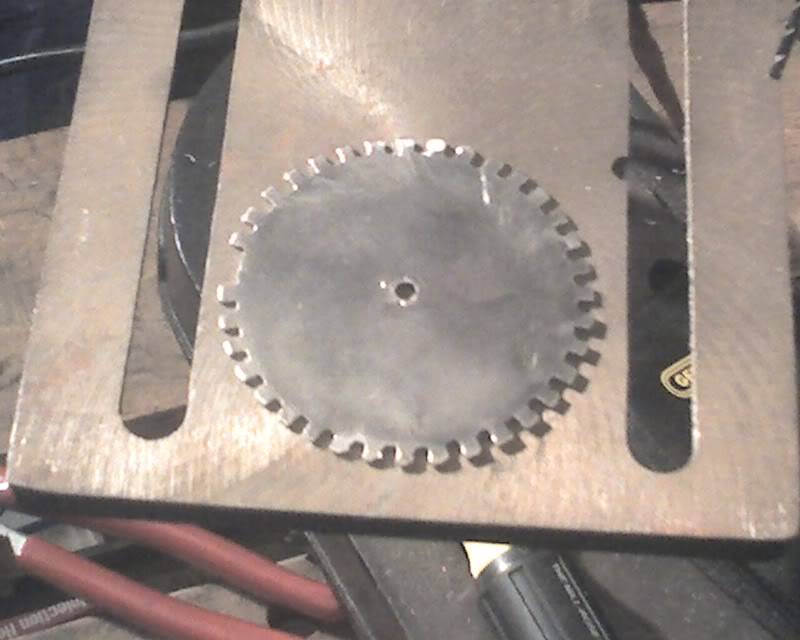
That first start took a while. At first, I thought I’d found the problem. I missed the bit in the manual that said the missing tooth needed to be 90 degrees behind the sensor on a four cylinder and I had it set as if it were a V8, 50 degrees behind the sensor. Easy enough fix, but it wasn’t much better. I tweaked it mechanically and with the trigger offset setting in MegaSquirt, but nothing got it going. It continued to, at best, spew smelly exhaust fumes out through the throttle bodies, which I suppose isn’t quite right :) I verified that plugs on both coils were sparking and at different times. I researched firing order, mostly just to ensure that my assumption that it would be 1-3-4-2 was correct. That finally got me thinking about the coils and I started checking the wiring. Even though I thought I’d carefully translated all the wiring diagrams, I still managed to swap the ignition coils. Switched two pins in the connector, hit the starter, and Buzz sprang to life.

Well, not perfectly, but running. It’s a surgy idle. MegaTune showed that the ignition advance was swinging pretty wide, in time with the surges. The tuning tables in MegaTune are grayed out (an issue that I knew I would need to address at some point, but just hadn’t done it yet) so I couldn’t adjust the spark advance table. To determine if MegaSquirt was swinging the advance, I disconnected the SAW lead, but the surging continued, indicating that it’s a fueling problem.

Tonight, I hope to add a switch to the reload jumper. Pulling the ECU out to take the cover off and set the jumper to reload code (which will probably be needed to fix the table gray-outs) would be a major pain, especially now that the EDIS module is in there, too. While I’m there, I hope to add a short serial connector so I don’t have to keep this six footer rolled up in there permanently.

Deliverymen bearing gifts…


I received two packages today, one with the silicone intakes (I swore I ordered the blue ones, but they are black and the order shows black. Oh well…) and one with the bank angle switch.

The intakes are about the same length as the neoprene ones I have now, which I pretty much expected

I also spent some time at work redrawing the trigger wheel with thoughts of sending off the order to eMachineShop.com. When I got home, however, I tore into the project and have produced a reasonably good trigger wheel made from 16ga steel I had laying around from an armor project. It seems reasonably well balanced for hand made.

The current mounting is a significant compromise to the plan. I found a scrap of material that is the proper length, but not really the proper diameter to fill the space between the crankshaft and the trigger wheel. It is functional, but I suspect it may not be very robust. I intend to return to plan A, though I may need to start and run the engine before then. Once I have verified that it is properly placed, I will apply threadlock and/or lockwashers to secure it until I can implement the proper spacer.

My biggest concern is that the 16ga steel may not be massive enough to generate a good signal. With the wheel in place as shown above, it generates a signal that of about 0.485V when cranking. In the MegaManual section on EDIS, it indicates that 0.5V may be the minimum usable signal.

We’re planning on riding this weekend, so it will probably be Tuesday night before I get another chance to work on Buzz. At that point, however, I will be ready to wire up the EDIS module. It has occurred to me that I can probably use the stock coils, at least temporarily, if I can’t acquire a Ford coilpack between now and then. With a little luck, I can put the EDIS module physically where the stock ignitor is, especially now that there is a smaller fuse panel there.

Filters and Trigger Wheel


The filters are a tight fit for the space where they go, especially on cylinder 4. I’m glad I got the oval filters, which are substantially narrower than the round ones, so the filters clear one another horizontally, but cylinders 1 & 4 filters are resting against the frame. I’m hoping that the overall length of the silicone intakes I ordered will be shorter, which will help this fit a lot. I could trim the neoprene ones, but I figure, “Why bother?” They will be replaced soon enough. It’s possible that I may also need to shorten the metal intake adapters that I built. I hope not, if for no other reason that it will be a pain to do.

I may also need to reroute the fuel line from the tank. The fuel filter is currently nestled between the air filters for cylinders 1 & 2. Not only does it interfere with the mounting position, and thus the appearance, of filter 1, it also makes the filter essentially hidden from the rider view from the saddle.

What might be more useful to the rider is some visual verification that fuel is flowing. I can find lots of flow indicators, but they are all huge industrial things. The search continues…

Speaking of fuel flow, I have determined that the petcock, even if it were opening properly from the vacuum, doesn’t flow enough fuel. The filter stays dry as long as the pump is running. Though fuel pressure on the high side of the pump doesn’t seem to suffer, there should be more flow for pump cooling purposes.

I pulled the stock ignition reluctor thingy. Something I didn’t expect, so I am thus glad to have discovered now, is that it’s not a flat plate mounted directly to the end of a crankshaft. Rather, the plate has a integrated spacer between it and the end of the shaft. To duplicate the dimensions of this spacer using a flat plate for my trigger wheel, I will need to make a fairly simple spacer, 1″ in diameter and 11/16″ (0.685) thick. It could be aluminum or steel, even a heat resistant plastic. My trigger wheel should work at 1/8″, although to ensure the strongest signal, I should probably make it more like .20″ thick.

The spacer will need a slot cut or a hole drilled to mate with an alignment pin that is in the face of the crankshaft end. To secure the alignment of the plate with the pinned spacer, I will drill two diametrically opposed holes in the plate. The plate will be held by the bolt while the system is initially adjusted. Once the proper alignment to TDC is determined, then I will drill through the two holes into the spacer and apply roll pins or some other sort of peg for positive alignment.

The one thing I can’t seem to find supplied new is the connector that will be needed for the coil pack. That alone is enough to make me want to get the coil pack from a wrecking yard so that I can salvage the connector from the wiring harness. It may also be a good idea to get the inertia switch from a Ford that disables the fuel pump in a collision. Chances are the same vehicle will have the coil, connector, spark plug wires (need the coil end connectors) and the safety switch.

Speaking of safety switches, I forgot to mention yesterday that I won a minimum bid auction for a Honda Goldwing bank angle switch, intended to disable the fuel pump if the bike lays over. Presumably, I could use only the angle switch, assuming that a collision would also put the bike on it’s side. I’ll think about it.

Tach Input Issue


My K&N order arrived already and I have ordered the silicone intake reducers with clamps…

But, the tach input thing… The diode thing didn’t work, but I think I have figured out why. Anything that connected the two coils to each other caused the engine to die pretty much immediately. I used multiple diodes, low and high value resistors, capacitors. Didn’t seem to matter. Anything that allowed any electrical signal to cross from one coil to the other failed.

I would need a working ‘scope to verify this and I own one but haven’t seen it in years. Maybe it was lost in a move or maybe it’s buried in the storage building. Anyway, I think all these coupling experiments failed because the ignition unit may output a burst of high frequency pulses for each spark rather than a single DC pulse. It’s probably well beyond the frequency response of the tach input, so MegaSquirt still sees it as a single pulse. I suspect that this burst may also be over 12V, but if so, my meter can’t catch it.

In short, this means that, in order to use MegaSquirt properly with the stock ignition, I will need to use optoisolators and OR their outputs together.

What would probably be better is to go ahead and convert the ignition system, since I plan on doing that anyway. I was hoping on getting the fuel system fairly well tuned before adding another complex issue, but what the hey…

The primary task to accomplish for the conversion is the construction of the trigger wheel. I should be able to do that with a little bit of jigging and my drill press.

I will also need to purchase the appropriate coil pack. High performance units can be had from Summit Racing for $60, stock replacements from AutoZone for $45 or salvage from $10-$30. I’m leaning towards the Accel unit, though salvage is probably fine and would include a connector. I will need the $15 wireset, too, but will probably need to cut them to length and/or change the plug connectors.

Took a spin…


Over the last couple of days, I’ve been thinking of points of summary that I want to share about the project. This post may therefore seem to have a rambling quality to it.

The CLT sensor mounted where it is, just inboard of the #2 spark plug, seems to work well. Once it indicates 140 degrees and I take it off fast idle, it’s pretty well warm. I may move that point up a few degrees this winter. I will have to see how he runs. I also need to find/build a proper cable so I can use the stock choke lever to operate fast idle. As it stands, I have to manually operate the cam and hold it during the warm up period.

The fuel tank return went well. I had to completely reroute the fuel lines to get flow from the tank. I had to use the old original vacuum line to operate the petcock, but the rubber has hardened and doesn’t seal very well at the tap (cylinders 2&3 teed’). I had to leave it in the PRI position to get fuel to the pump. At least there’s no float valve seat to worry about, not as such anyway. I’m pretty sure I have more vacuum line to replace it; I just couldn’t find it Saturday afternoon!

So, once the fuel tank and seat were on and the brakes refilled and bled (see brake detail below), I took Buzz for the first ride on MegaSquirt and in fact, the first ride at all since last January. Having ridden Ruby all this time, it took a bit to make my feet go the right places and directions. I had trouble finding the rear brake and in fact, had a millisecond of panic while rolling leisurely down the driveway. :D But, everything came back pretty quick and as I rode off, everything seemed to be working well enough. I found pretty quickly, however, that I could ride very gently without issue, but beyond a certain (small) throttle opening, it just didn’t work right, bogging down. I could reach the 45 MPH speed limit at a socially responsible rate, but not in any kind of a hurry.

By the time I was on my way back home (ran about 4 miles total), I could detect a faint smell of gasoline when stopped and was worried about a leak. Also by then, the intake reducers had softened somewhat from engine heat (see intake detail below) and I was somewhat concerned that they might fail.

Back in the driveway, I could find no evidence of a leak, but I could smell fumes from around the tank filler cap. I opened and reclosed it; maybe it wasn’t seated well. Even though the intakes had softened a lot, I think with the weight being carried by the mounting bracket, the intakes would probably not fail, at least not in the short term.

It was time to button up the garage, get myself cleaned up and go pick up my Lovely and her Mom at the airport; they’d been away on a trip all week, which is one reason I had so much time this week to dedicate to this project.

In the time since Satuday, I have figured out two things about the tach input. First, it’s reading half speed because I’m only connected to one of the two coils. I misunderstood what the tach input wants. I guess at some level, I was thinking about a timing light picking up a single pulse from cylinder 1. Connecting both coils to the tach input is pretty trivial, using diodes to isolate them from one another. This will get the tach reading up to reality and with a few minutes’ spare time, I hope to get that done this evening.

I also underestimated the value of a proper tachometer data. I figured it was a go/no-go thing at most. However, without a mass airflow sensor, MegaSquirt has to calculate the volume of air going through the engine to know the amount of fuel to provide. This calculation depends primarily on two things, the constant representing the displacement of the engine and (you’ll never guess) the RPM! The tach being at reality should mostly fix the worst problem I experienced in my 4 mile test ride Saturday afternoon. As you will recall, the bike seems to run pretty well at very modest throttle openings, but bogs tremendously at much over what I suspect is about 5% throttle. Upon reflection, I’m sure that MegaSquirt was only providing enough fuel for half the rpm that the engine was actually running. Makes perfect sense! I’m trying to run 5000 RPM and MegaSquirt thinks I’m only running 2500, and so only gives me half the fuel I need. At lunch today, I spent $1.07 for two diodes that, once applied, should fix this problem.

The throttle cable, while not exactly in the greatest location, is at least not as interfering as I may have expected. With the tank in place, the throttle cable just protrudes from under the tank. Under exactly the right conditions, I feel the throttle body vibrating against my knee. I still want to fit a plate over the assembly to ensure garments don’t get snagged on the throttle cam.

I have ordered air filters. I bit the bullet and got K&N’s, though I got about the cheapest K&N’s that fit. Other filters just don’t have the reputation that K&N has. In the same order, I also got air filter cleaning/oiling supplies, oil filters and a couple of decals. I may see if I can get decals for all my suppliers (you know, companies from who’s products I’ve robbed parts off of, Suzuki, Kawasaki, Ford, hehehe) and decorate only the side covers with them. The filters are a set, part number RU-1824. There are 4 tapered oval filters with 52mm offset flanges. I think that will be the most effective use of the available space.

The neoprene intake couplers got pretty soft during my short ride. By the time I got back home, rather than only the coupler pulsing like a panting lizard, the entire throttle body assembly thrusts in and out by a few millimeters. I have found reinforced silicone intakes that I will order once I have verified the dimensions. I thought I remember them as 1.5″ x 2.0″, but I didn’t want to place a $50 order and have it be the wrong thing. These are probably the same overall length, so I probably won’t need to redo the throttle body mounting braces. These should be quite a lot stiffer than the plumbing parts.

As for a few non-EFI issues, I got the brakes back in operation, but something is definitely amiss there. Actually, the front brake has been a little iffy on Buzz ever since I’ve had him. The brake’s never had the power it should. I’ve had an unintentional antilock brake because it simply won’t lock up. It stops, though, and that’s helpful.

The forks feel a bit soft, too. I need to verify that everything else is normal, but there is an oily dusty bathtub ring on the downtubes, so I think the fork seals need replacing. Consequently, chances are that it’s a few millimeters short on fork oil.

There is a rubber guard that ideally supports itself and keeps the chain from throwing oil up where it can be seen, directly above the shift lever. This rubber part doesn’t like to stay on and fell down into the drive sprocket. Judging by the sound and feel, I think it’s been summarily chewed up. By the time I was back from my ride, I’ll bet it’s been spat out, as well. This general vicinity probably needs some long term guard applied to ensure that MegaSquirt wiring never gets into the chain.

Cold Starting and Manifold Inadequacy


I don’ think the two are actually related…

One thing I will need to address soon isn’t much of a surprise. The neoprene reducers that I use to adapt from the throttle body to the intakes is far too limber, especially once it warms up. At idle and especially when reving down (high rpm, throttle closed) they pretty much collapse under the vacuum. I’m also concerned about the intake side weakening from the heat and perhaps leaking, or more likely, failing catastrophically and inducing a severe lean-out condition in that cylinder. I have in mind a simple brace to help the collapse problem until I can replace these boots with more rigid components. I also have a crazy idea for something I could fabricate, basically a homebrew manifold.

As for cold starting, I knew I had other things I needed to do today, so I didn’t bother getting the laptop and everything al connected up before I started the bike this morning, but I will definitely need to adjust the warmup enrichment. It was hard to start and hard to keep running, but once it was warm, it did fine.

In my other rat killing, I stopped at the shop and got a valve for the fuel return. I may get a chance to install it tonight so that I may be able to take Buzz for a spin soon, assuming that getting the brakes back online isn’t a major undertaking.

Much much better….


After just a little tweaking, things are much better.

The change he seemed to like best was switching to 2 squirts per cycle simultaneous. This smoothed out a lopey idle that I was about to blame on the plugs. They are in need of changing, anyway, so I’ll do that. The ignition system on these bikes are notoriously weak, so when I get it switched to EDIS, things will probably improve again.

Other than that, there was a hesitation on reving. I looked at the Acceleration Wizard and found what I presume was the default setting to 100% TPS based. I merely moved the slider to the center and the hesitation is gone.

The engine seems to be running well enough that I can likely do little more tuning before I can ride it.

Riding it is held back by two things. Primarily, the tank is currently off. I need to fit a return line to it and I don’t want to do that without a valve for it. I will visit my neighborhood shop (which has been very helpful in this and other projects) tomorrow and get an appropriate valve and fit it to the tank. I will also get him the part number for the K&N filters I want to try.

Of some concern about fuel, I saw somewhere where someone burned up a fuel pump because the stock petcock in their application could not supply fuel quickly enough to cool the pump. It flowed enough to supply the engine, but not enough volume to cool the pump. I’m not going to worry about that before it’s a problem, but I will be looking for it.

The other thing holding back a ride is that in the time the bike has been sitting unused, the front brake appears to have gone completely dry. There is some misting on the caliper, but it doesn’t appear that all the brake fluid leaked out, but nonetheless, there is none in the reservoir. Granted, for a test ride, filling and bleeding the brake system will be fine, but the actual problem needs to be addressed…

As I sit here typing on my laptop, which sitting a board across the arms of a camp chair within easy reach of Buzz, I’m filled with a great sense of satisfaction. I made it go!

Let’s not add up the dollars just yet….

It RUNS!


9/25/08 20:05 CDT It ran!

I had to dink with it a bit. I think there was still air in the injector line. Once it settled down, I can get it idle pretty well and it revs quick after an initial hesitation. I am working on that.

However, VERY elated that after all these months of delays that Buzz is running on MegaSquirt!

Fuel Pump 101


Ok, I figured out what happened to the fuel pump. I broke it, but not the way I thought in last post.

I now believe that the pump was not leaking when I first tested it. To minimize fuel spillage and to keep from having to remove the entire assembly to tape the pressure gauge threads, I used the ubiquitous ViceGrip pliers to pinch off a line in the spot where I would presumed the majority of drain-back fuel would have come from. After I powered the pump up, pressure did not come up and I noticed the ViceGrips still in place and powered it down again. I noticed the wetness from the leak when I was removing the pliers. With the pliers off, pressure came up as it should, but with fuel pouring from the pump.

I removed the pump today and have found the culprit. It’s a feature, not a bug. Pinching off the line where I did meant that the pump pushed full pressure without the benefit of the regulator to bleed off the excess. There is an over pressure relief valve on the pump and that is apparently where the fuel is leaking out.

It looks like a ball held down with a spring. I probed at it and now in operation it just seeps a little fuel, but it still leaks. I’m guessing that there is some debris in there keeping the it from fully reseating.

To get the project going while I have the time off work, I have decided to plug the over pressure valve port. I won’t be pinching off a line like that again and I will be shopping for a replacement pump because the over pressure valve really should be there, but for now I need to get this thing running!

I used brake cleaner, followed by acetone to clean and degrease the port. I mixed up some JB Qwik, the fast setting version of JB Weld and dolloped a bit in the port. I used a thin rod to stir and push the epoxy into the port and applied more, repeating until I was pretty sure there were no more bubbles in it. As I write this, it is sitting upright waiting to cure. JB Qwik is set in just a few minutes, but it says four hours to cure. It will be a loooong four hours.

One thing I will do during those hours is cranking the engine watching the coil leads to see where I need to connect the tach input. Hopefully. I may even try to run it on starter fluid enough to verify that MegaSquirt sees it spin.

Sluggy Blogs All The Subjects