Everyone Loves A Little Probing…

One of the many tasks the ESP boards can easily do is read the Dallas Semiconductor (now owned by Maxim) 1-wire devices, particularly the temperature sensors. A popular choice is a unit embedded in a stainless steel probe at the end of a waterproof cable a meter or so long.

The Dallas 1-wire protocol is fascinating and clever, but most importantly (if someone else takes care of the fussy bits) it is really easy to use. In the case of ESPHome and the temperature probe above, it is dead simple to connect and read a temperture, but even cooler, several such devices can share a single pin on the device.

For experimental purposes, I used my ESP32 dev board, which has solderless breadboard friendly pins installed, making it even easier to throw together a test system.

Not shown in the picture is the data bus pullup resistor. Because of the distance it needed to reach, from the 6th pin from the left on the top row to the far right pin on the bottom row, I could better fit the resistor under the MCU board with no jumpers.

After a couple of false starts because the IDE for ESPHome is really sensitive to indentation, I was able to identify the unique ID for this temperature sensor then start bringing in data from it.

dallas:
  pin: 21
  update_interval: 10s

sensor:
  - platform: dallas
    address: 0x693ca0e381b17528
    name: "Testboard Temperature"
    accuracy_decimals: 2
    filters:
      lambda: return x * (9.0/5.0) + 32.0;
    unit_of_measurement: "Β°F"

At the time I am writing this, I don’t know if pin 21 is special, but it was the pin used in the example I followed, so I kept it.

The first thing you do is install the block with only the ‘dallas’ directive and the pin number. The logs will show the address of any devices it identifies. Then you can add the rest of the configuration, complete with the actual addresses of any and all individual devices. Apparently, one can do a ‘default’ device read, but it will understandably fail if there is more than one device.

I played with the update_interval. For my testing purposes, the shorter to better. One thing I will use this board for is testing communication limits, specifically whether I can expect reliable WiFi connectivity in certain outdoor locations from these boards. Rapid updates of the data will help determine that.

The most interesting new skill learned was the lambda directive. This is a special calculation ‘filter’ of sorts. The hardware device reports in degrees C and lambda is used in this case to convert degrees Celsius to degrees Fahrenheit.

One of the practical uses I see for this type of sensor would be to use these probes for each of our non-kitchen refrigerators, one for the freezer, one for the refrigerator and maybe one for the ambient, if some other sensor doesn’t already provide an ambient temperature. I have found the door switches I like also provide a temperature.

Another could be to put various temperature probes into the HVAC system in the attic, return air temp, duct temp, attic ambient, evaporator coil, etc.

I may add one to the hot water meter to monitor the water tank temperature.

The Little Board That Could (and that one time I was an idiot)

I haven’t been excited about a hardware project in a while, mostly because I haven’t really had a practical application that needed doing.

We have a 400-something foot deep well that produces really nice water. It does have a bit of sand that we need to filter out and all that is pretty well addressed by now. According to metainfo on the pictures I took, I installed a water meter in our water system in May of 2012. I chose a unit that included a pulse output so that I could connect it to something to electronically track our water usage. The pulse output is really just a magnetic reed switch operated by a tiny magnet on the 0.1 gallon dial. It closes the reed switch once per revolution, thus ten closures per gallon. The pulse unit is removable and not pictured here, though you can see the magnet on the x0.1 dial.

Incidentally, between May 2012 and the time I am writing this, we have used almost 247,000 gallons of filtered water.

Unfortunately, nothing available to me did a good job at counting and accumulating those pulses, not anything I could buy for a decent price. I had an electronic counter connected to it for a while; it was just an accumulator with no connectivity to anything. It’s battery has LONG since died, but I disconnected it to connect the board described below. I need to put a new battery in it and see how far it got. πŸ™‚ There are professional data acquisition modules that do the task, but not for a price I was willing to pay. When I was shopping for stuff at CloudFree and saw these little ESP8266 boards, especially for $3.50 each, I looked into them. Wow.

The ESPHome project is an entire ecosystem built around a family of boards using the Espressif family of microcontrollers, ready to deploy in Home Assistant. In short, people way more brilliant than I am have done all the hard work and have modularized home automation functions so that with a few lines of configuration, one can set up these boards to do a wide variety of complex functions, interfacing with hundreds of off the shelf input and output devices. You can combine whatever you need in essentially limitless ways.

What mattered to me immediately was the Pulse Meter Sensor. It was original intended to attach to electric meters which provide a pulsing indicator for consumption, but by tweaking that default configuration just a little, it tailors it nicely for water.

After a bit of experimentation, the configuration to read my meter is as follows:

sensor:
  - platform: pulse_meter
    pin: 13 
    unit_of_measurement: 'gal/min'
    name: 'Water Usage'
    internal_filter: 100ms
    accuracy_decimals: 2
    filters:
      - multiply: 1
    total:
      name: "Water Total"
      unit_of_measurement: "gal"
      accuracy_decimals: 0
      filters:
        - multiply: 1

The decoder ring: Pin 13 is descibed in better detail below.

The ‘unit_of_measurement’ is just the text describing the units reported. It doesn’t actually change what the units are. You could call it ‘cubits of sanskrit’ and it would still give you the same numbers you configure it to deliver.

“internal_filter” is essentially a debounce timer in this application. It tells the counter to ignore any pulse shorter than 100ms.

The accuracy_decimals directive is the number is digits right of the decimal to deliver. The meter rate is calculated as a rate per minute, so it basically measures the time between pulses and calculates the rate based on that. So long as water is flowing, it’s reasonably accurate. Kinda weird that once you turn the water off and its not getting any more pulses, it still reports the same flow rate because it’s not changing. There may be a setting to address that. If you wait long enough, the rate drops to 0, so there probably is a timeout value.

Since my meter outputs one pulse per gallon, the ‘multiply: 1’ lines are redundant, but I left them in from earlier failed experiments and for clarity.

For ‘total:’ this is a running total of gallons consumed. Since it is always in whole gallons, there is no need for accuracy_decimals and again, muliply by 1 is just there for clarity.

My board looks almost exactly like this one:

There is a little confusion (for me, anyway) as to what one should call the various pins and which ones are ok to use under what conditions. Some of these pins are asserted internally at boot time; some will cause boot to fail if they are asserted externally. Some are used when communicating with the chip. Long story short, the four pins highlighted in green are generally safe to use under all conditions. I am not sure why I chose 13 instead of 15. Shrug. I am equally unsure why the board designers put D0,D5,D6,D7 & D8 for GPIO 16, 14,12,13 & 15. I’m sure there is an engineering reason. Whatevs.

I put a 10k ohm resistor between D7 and 3V3 to pull the GPIO13 pin up, then connected the pulse output between D7 and GND. It works perfectly.

Flushed with this initial success, I decided to add a second pulse meter sensor to this same card. The water meter above is after all the water filtering, right before the treated water goes into the house. I have also tapped off before the filtering to feed water hoses outside with significantly higher pressure and flow. This water is, of course, not metered. I have another meter very similar to the one feeding the house, but this is not such a critical feature and I don’t really need the ‘odometer plus pulse’ meter. I can really get buy with just the pulse counting. Besides, that other meter was really intended to be a spare for the ‘main’ meter.

I found a cheap water flow sensor on Amazon and as I write this, it (two of them, actually) are due to arrive tomorrow. Plumbing it in should be pretty simple. The ESP8266 board has 5V available to power the flow sensor. Wiring the input will be a little more complex as the flow sensor is a Hall effect device with a 5V output and the ESP8266 board has a 3.3V input. They are reputed to be fairly 5V tolerant, but even a $3.50 board doesn’t deserve to be smoked just because it’s cheap. The easiest way to accomplish this level shifting, especially with the fairly low bandwidth needed for these frequencies, is a simple resistive voltage divider network.

Whatever value chosen, R2 will be (so close as it doesn’t count to) twice the value of R1. I will probably start with the venerable 10K for R1 and likely two 10K in series for R2, because I have a cubic buttload of 10K resistors laying around. If the output of the 5V system is indeed 5V, then the junction between R1 and R2 will be 3.3V. The only factor that might affect that is if the 5V output can’t provide enough current or if the input for some reason sinks a lot more current than anticipated. In all, it’s expected to be fine.

If I understand the specs correctly, this flow meter gives a frequency output of 5.5 x the flow rate in liters per minute. Those multiply lines in the sensor config will mean something now. I have done some scratchpad math and arrived at the following pulse meter configuration:

  - platform: pulse_meter
    pin: 12
    unit_of_measurement: 'gal/min'
    name: 'Unfiltered Water Usage'
    internal_filter: 100ms
    accuracy_decimals: 2
    filters:
      - multiply: .048
    total:
      name: "Unfiltered Water Total"
      unit_of_measurement: "gal"
      accuracy_decimals: 0
      filters:
        - multiply: 20.82

As I write this, I cannot recall exactly how I came to these two multipliers, but I know that 3.78 liters per gallon and 5.5 x the flow rate were both involved. I strongly suspect that some empirical testing will be in order as well.

Also, a chart I saw indicated that at some higher flow rates, the output can be 60Hz or so. This will be getting pretty close to the 100ms internal filter pulse width. On the other hand, hopefully the Hall effect output is already debounced, so that filter may be redundant. We will see.

Furthermore, I will also be adding a flow sensor to the inlet of the water heater to monitor hot water usage, with it’s own board. Perhaps I can be clever enough to subtract that amount from the total usage somewhere.

The time has come for my confession.

I have described the ESPHome experience as it should have been, almost plug and play. It did not go that way and it was NOT because of ESPHome.

I was very excited to get that first board plugged in and make it go. The process sounded very straight forward.

Install the ESPHome Dashboard on Home Assistant. Trivial, done.

Open the ESPHome Web UI, click on Add Device…

Ooops. Well, no BIG deal. Adding an SSL certificate is something I need to do someday, but I can just do this from the PC I’m using instead, so I click on the ESPHOME WEB link.

I get this page, I plug in my cable with the board, click on the CONNECT link and this is the last time anything good happens for a looong time.

It pops up a dialog wanting to choose a device to connect to, but none of them look like anything new or appropriate. I open Control Panel and nothing in Device Manager looks like a new thing, except for that one thing that says it’s not functioning because Windows can’t find a driver for it. I unplug the board, it goes away; plug it in, it comes back. Sigh.

I Google, find the [hardly sketchy looking at all Chinese] driver download page, run the self-installing driver, hoping that all my anti-virus software is up to date. It appears to install.

No change.

I try it on what eventually turns out to be three other computers. Nothing different. And apparently no viruses. Win?

Finally, something I *swear* I saw somewhere suggested plugging it into the Home Assistant hardware to try it from there. Maybe I dreamt that. I had more ports in the USB hub, so I plug it in. I consult the VM to see if it is there and ready to be allowed over. No, just the Zigbee and the Z-Wave.

I wonder if somehow I am limited to two devices by the virtual machine manager, so I unplug the Z-Wave dongle and plug the ESP8266 back in. It still doesn’t show up anywhere.

To be completely honest, the ESP8266 and the Z-Wave dongle were alternatively plugged in and unplugged multiple times during this process, sometimes both plugged in, sometimes to the hub, sometimes to the front panel USB. I probably put one of them in my ear and the other in my anus at some point, just to see if that would help.

By this time, I have spent a few minutes here and there during three hours of the workday and four solid hours that evening trying to get this awesome little board talking and I’ve reached a point where I am both too tired and too frustrated to go on, so I put it away and do something else for a while, probably involving alcohol.

The next evening, I start in on it again, but my fresher eyes realize that I did all this testing with the same presumed good USB cable. Afterall, it definitely shows up when plugged in and goes away when unplugged, it just couldn’t find the driver for the device. So, I walk 8 feet across the room, grab a different USB cable and plug it in.

Comes right up, CH340C on COM3. ESPHome sees it, connects, uploads adoption code. Everything I do with it from this point forward works like it’s supposed to. I try the ESP32 board, works perfectly, but it’s drivers (CP210X, like the dongles, ironically) are already installed in Windows.

All because the F&*%ING USB cable was not 100% bad.

[insert all the ESP8266 success story related above here > ]

NOOOOOOWWWWW…….

A couple days go by and I notice that the driveway light switch, the lone working Z-Wave device currently on Home Assistant, is not working. I have a Zooz multirelay configured, though not deployed, but it is also not working. When I dig deeper, I find that the controller is down. As I’m sure you can predict now, I spend several days trying various things to get the stupid dongle to come back up. I even reach a point where I am contemplating abandoning all Z-Wave and going all WiFi and Zigbee. It’s not a trivial decision; I have a box full of unopened Z-Wave stuff, including a spiffy new scene controller I have just purchased that I have specific plans for.

I was able to verify that the dongle itself was working. The Silicon Labs tools included some network stat tools where you could view a count of packets send and received. I had it installed in my laptop, took a snapshot, waited, took another, waited, etc, just to verify there was no regular traffic. Then I plugged in a multirelay device and there was a burst of traffic between it and the dongle. Reasonable expectation of functionality.

Among the things I tried was viewing lsusb and dmesg from the terminal of the VM. Trouble is, because this is Alpine Linux, this isn’t really lsusb and dmesg binaries but their lobotomized BusyBox equivalents, so most of the usual switches that could add more details to help figure stuff are not really there. Not that I am any kind of ace at troubleshooting Linux issues anyway. I have had the perhaps unenviable position of being more of a Linux power user rather than a sysadmin. My (mostly Fedora) systems have for the most part always just worked and I have rarely had to fix anything on them, so I don’t have just tons of breakfix experience with it. If it doesn’t break, you never need to fix it.

In any case, it turns out that the “solution” appears to have been to let something time out. The last thing I did was a reboot of the VM with the dongle removed. I added the dongle to the USB hub, but for whatever reason, I didn’t immediately allow it through to the VM. Some undetermined time later, a day or so, I sat down to prove that I am indeed insane only to discover that it needed to be allowed through to the VM. I did it and suddenly, lsusb listed another CP210 device and dmesg showed a new USB device found and Z-Wave JS UI showed /dev/ttyUSB1 available.

Now it works again.

Home Assistant: The End of Vera?

Since about 2012 or so, I have been working on some home automation, mostly using Vera (which has changed names again, kinda) and a handful of Z-Wave enabled switches. It has never really taken off like it could have at our house, but I do have a few bits in place that we have grown to appreciate, especially once I deployed a few Amazon Echo devices and we could ask Alexa to turn some stuff on and off for us.

The three things that see use multiple times every day are plug modules that run lights and a ceiling fan in our back yard, a smart bulb in a bedroom lamp and the thermostat on the house HVAC system. Less often, but still seeing occasional use are two wall switches running a driveway light and front porch light.

I do have a smart plug strip that sometimes sees seasonal use for Christmas decorations and a generic plug module that right now is running the pump for an above ground pool, but I’ve used it for other short term uses as well.

As explained in a very old post, the DSL internet we had when we moved out here was not reliable enough for a service that was 100% dependent on cloud connectivity. MiCasaVerde’s “VeraLite” product had cloud connectivity to allow one to control it from elsewhere, but the actual control is local – not dependent on internet connectivity to work at all – so it seemed a good choice.

During the decade since then, I would occasionally add a device, but what was usually the biggest limitation was a less than perfectly reliable Zwave network that needed occasional rebuilding until I installed the version of Vera controller I have in place currently.

Zwave also had some difficulties with the size of our house. Ironically, if I had replaced every switch in the house with Zwave switches, the mesh networking protocol probably would have been much more robust, but with two wall switches side by side and one thermostat 30 feet from them, there probably just aren’t enough nodes for the redundancy.

Once we had linked Alexa and had grown to “depend” on controlling the thermostat verbally, having to reconnect it to the network every month or two became tedious. The then-new replacement Vera controller had Zwave and Zigbee and more memory, so I upgraded it and got a new thermostat that connected via Zigbee. It looked nicer and was much more reliable, needing to be reconnected to the network only two or three times a year. Afterall, the thermostat was the only Zigbee device in the house, so it there was a mesh network consisting of exactly two devices.

One time when I had great difficulty getting the thermostat to reconnect, I reached the conclusion that either the radio in it or in Vera had gone bad and as the only two Zigbee devices in the house, I elected to change the thermostat again, this time going to a WiFi device. Unfortunately, and as is almost inescapable anymore, it is a cloud dependent device, at least as far as remote control of it goes. Sigh…

Now that the thermostat is WiFi , the only Zwave devices left are the two wall switches that run the porch light and driveway light. Those are thus also the only remaining need for Vera. Everything else can be, and largely is, controlled by some other means.

Not locally, I might add.

I was at a crossroads.

Do I keep adding piecemeal to the mixed tech automation I have now? Alexa *kinda* ties it together, but only because Alexa has various skills that talk to Smart Things (my WiFi switches) and Geeni (smart bulbs) and Honeywell Home (thermostat) and Vera (Z-Wave switches). They all work slightly differently and none have any real automation other than basically on or off or maybe some simple scheduling.

Do I drop Vera and replace those only two switches it still directly controls and go with all WiFi/cloud automation or do I really do the hard think and get completely away from the cloud, which would probably mean changing my thermostat *again* and implementing a local controller?

Sometimes, it takes a while for me to write a blog post; day job an’ all. When I wrote those last two paragraphs a couple of weeks ago, I must admit that I was already elbows deep in replacing Vera with Home Assistant. Vera is already unplugged. However, at that time, I was still planning to move Z-Wave over and even expand Z-Wave devices in the house. For one thing, I still have a box full of undeployed Z-Wave devices that I purchased over the years. Also, Z-Wave power switching devices seem to be more likely to include power monitoring features. Not exclusively, but Zigbee devices just seem to include power monitoring way less often.

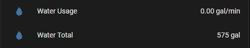
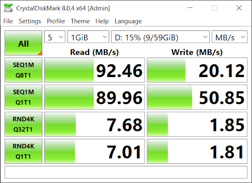
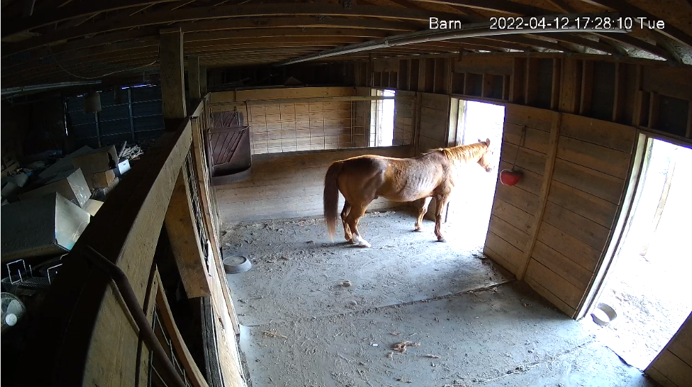
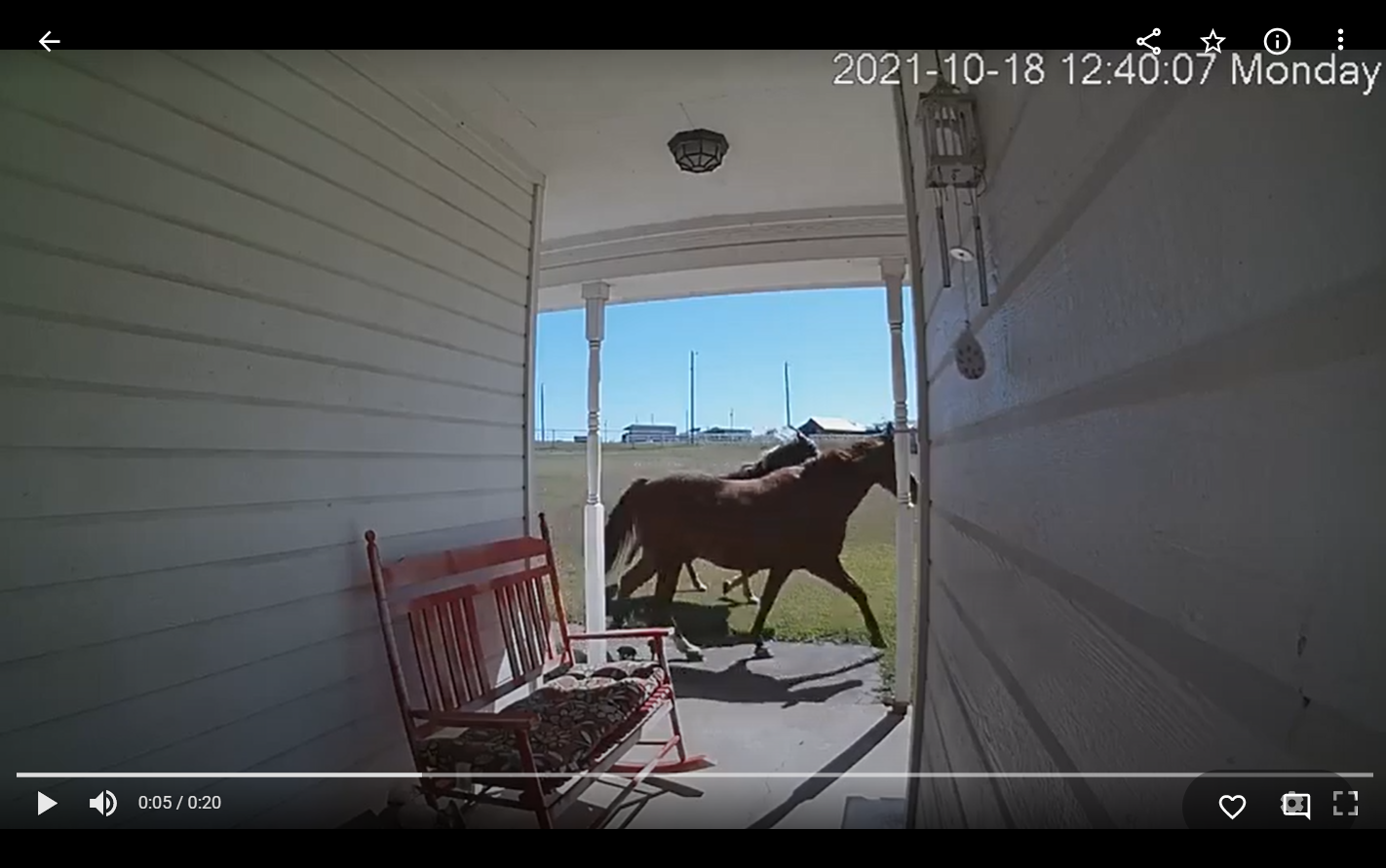
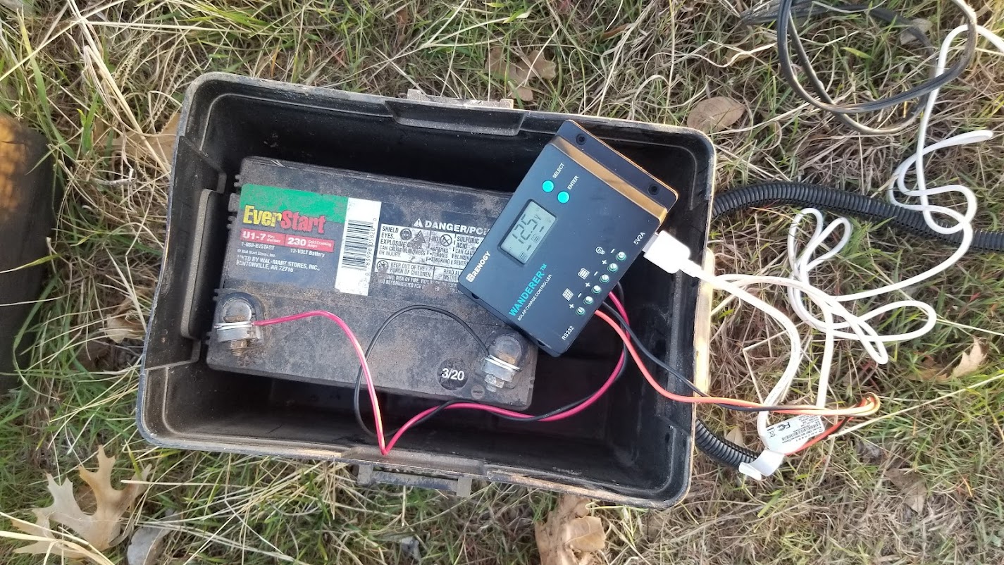
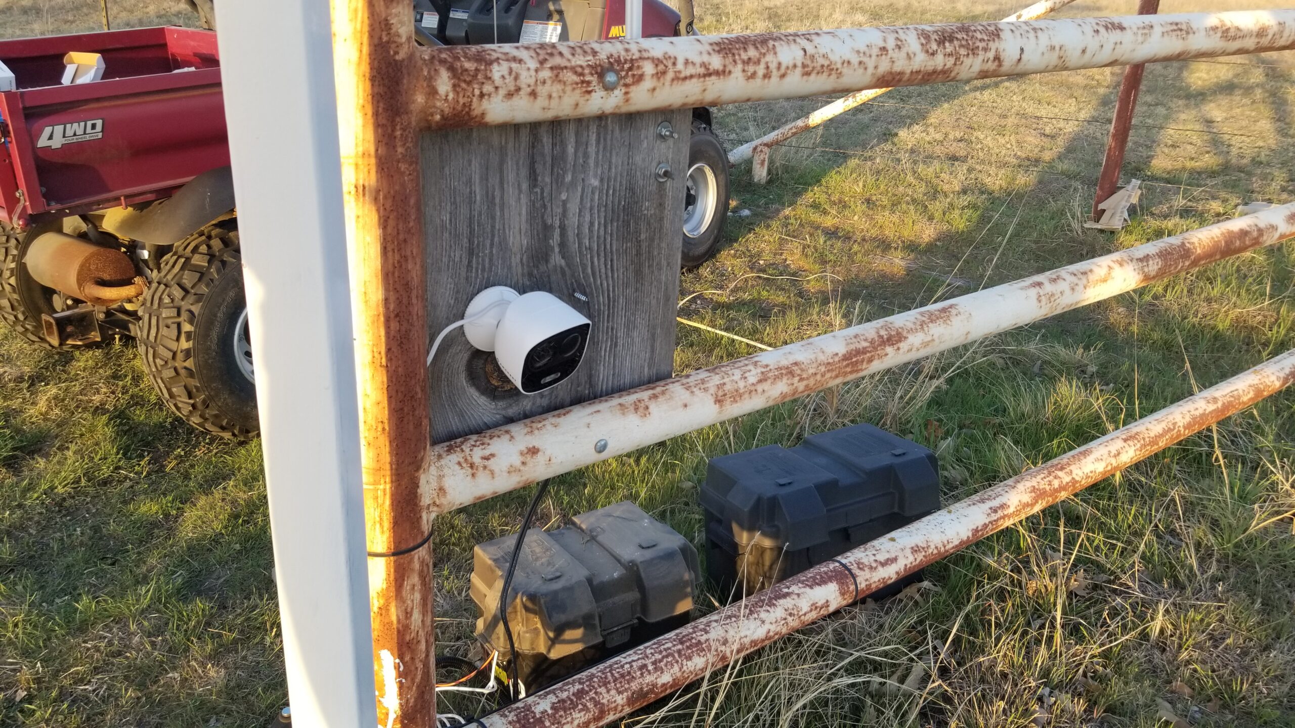
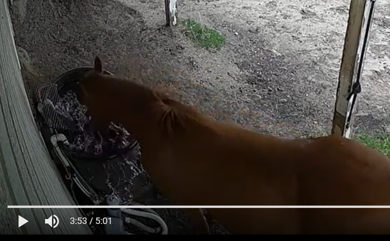
Power monitoring for the sake of power monitoring is not my goal for most of these devices, but for two or three of my applications, I use power monitoring to verify that the device is indeed operating. I use two heatlamps to mitigate freezing of some water system components and a tank heater and recirculating pump for the horses’ water trough. If they are switched on, but *not* drawing power, they need some kind of attention. The Z-Wave smart plug devices I have used in the past have power monitoring, but Vera didn’t really give me any way to leverage that into some kind of action item if it were to suddenly go away.

I’ll stop here to describe my Home Assitant path thus far. I was made aware of it by a friend while we shared a ride to and from Colorado for a firearm competition event. The advent of regaining local control is what really sold me on it, but between the demise of MiCasaVerde (the original company controlling the Vera line of controllers) and the new Ezlo company that has largely taken over that space with what may be limited support of the older hardware and software, I prefer to go in the open source direction. Yeah, I won’t have a customer service rep to yell at, but with most big well supported open source projects, you don’t need to. Somebody somewhere has probably already had your problem and fixed it. You just need to be good at Google to find it.

Home Assistant is usually deployed on a Raspberry Pi, but it is certainly not limited to that particular hardware. At the time I have gotten interested, Raspberry Pi 4 boards are in high demand and rarely in stock anywhere for more than a few hours at most. The only Pi boards I have on hand are probably Pi 2 at best, which is not enough Pi for Home Assistant. While other hardware options might work as well or maybe even better, I chose first to try using a Docker container hosted on my Synology DS220+ NAS since it is not really worked very hard and has plenty of leftover CPU power.

It came up quickly. Almost immediately, I wanted to add HACS, the Home Assistant Community Store, for an add-on to interface with my Emporia Vue account (yet another cloud based service… sigh). Installing HACS in the container required being able to run wget from the console, which was not installed in that image, which itself took a bit to get to, so I picked up a couple of (soon to be forgotten again, I’m sure) skills there.

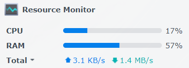
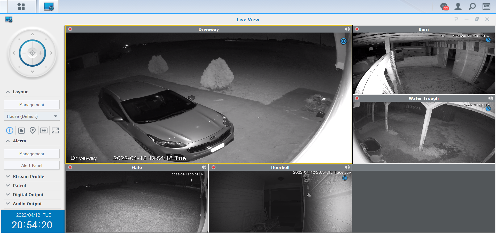
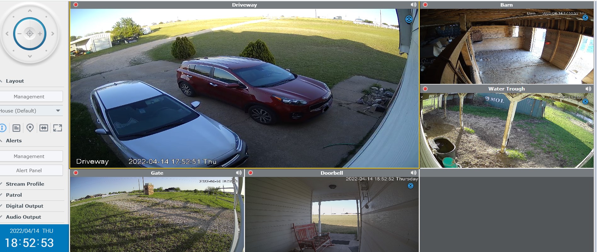
I ran up against other container version limitations pretty quickly, particularly when it came to adding drivers for anything I might need to plug in, like Z-Wave or Zigbee bridges, so after about 2 days, I elected to upgrade to a VM version, still hosted on the NAS. This is with it recording five cameras and running the VM:

This has worked out much better. It’s running Alpine Linux, a lightweight distro. You would almost never need to even know that unless you royally screw something up. Don’t ask me how I know.

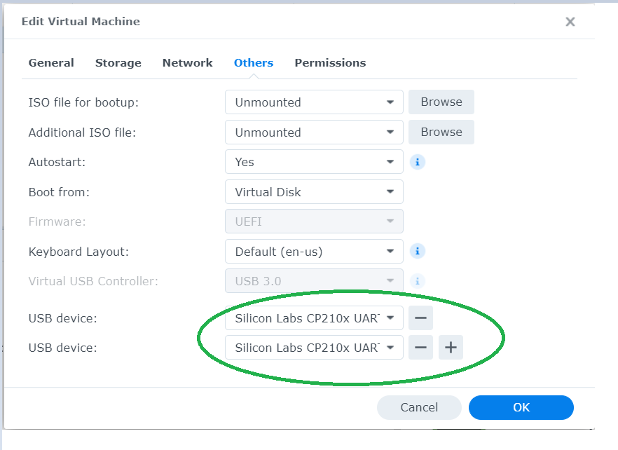
I acquired a Sonoff Zigbee controller and an Aeotec Z-Stick 7, both from general recommendations gathered from various Home Assistant YouTube videos and generall Googlage. These are connected to the Synology NAS via a USB 3.0 hub and they are powered by the NAS.

There was one concern with the Aeotech dongle regarding a required firmware update. The process for that is convoluted, but not particularly difficult. Just a lot of steps. Basically, you download a set of tools and a firmware image file from the chipset manufacturer, Silicon Labs. This requires, of course, a free developer account with Silicon Labs. Once the pieces are in place, it’s a 3 minute job. Curiously, once done, if you try to do it again, it gives you a scary error and aborts, but apparently this just means it has already been done. It is, afterall, a tool for developers, not end users. There are tools there that would also help me later verify that I did not indeed fry my Z-Stick. I’ll get to it…. πŸ™‚

Hardware-wise, the VM passes USB devices through to the guest OS when configured to do so.

As luck would have it, both Sonoff and Aeotec use the same family of Silicon Labs USB UART chips, which would eventually cause some confusion, but lets avoid that story as long as possible. We will continue to pretend that I was never an idiot and that Zigbee came up on ttyUSB0 and Z-Wave on ttyUSB1 and that all the stuff worked fine!

Actually, Zigbee never gave me an ounce of trouble. Well, maybe an ounce because of the geography of our place and where I want devices.

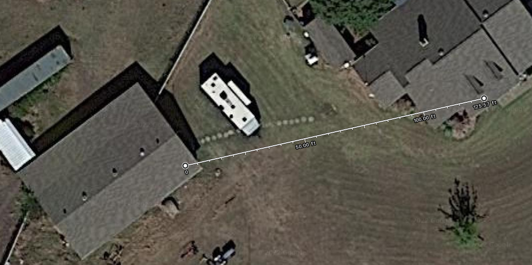
Some of the things I want to control and automate are in our barn/workshop, which is, at minimum, about 80 feet from the house. Realistically, the path from the Zigbee controller to the light switch in the workshop is more like 125 feet.

Zigbee allows exactly one controller in the network. Everything else is an endpoint or a router/endpoint. This means that to reach to my workshop, which incidentally has awesome ethernet connectivity, I must find a way to add Zigbee devices to bridge an RF route out there, completely ignoring that existing robust and reliable communication path. Remember how I mentioned that with open source, someone has usually already solved your problem? Apparently not this problem.

On the other hand, Zigbee, being a mesh network protocol, does work pretty well if you throw enough devices at it and place them cleverly.

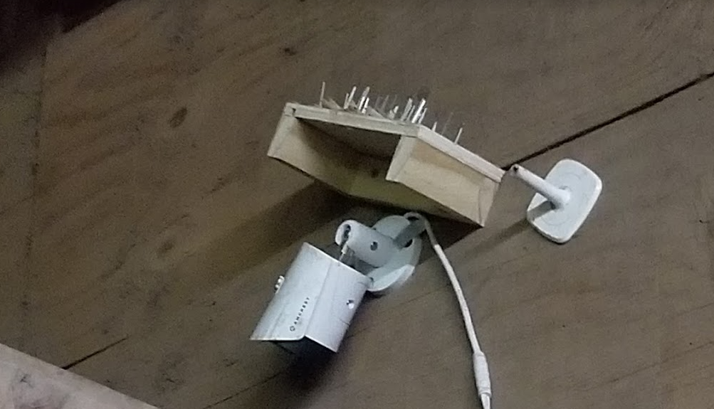
I took two strategies to extend a reliable Zigbee network to the workshop. First, I equiped the controller with a directional antenna, pointed towards the workshop. This puts as much RF energy as is practical in that direction. So far as I can tell, the existing Zigbee devices in the house suffered no change in signal strength. Apparently the side lobes on this antenna are good enough to cover the rest of the house. This antenna alone was enough to let one test device connect out in the workshop, at the full 125 foot distance, although the signal was down in the double digits, on the scale of 0-255.

The second leg of the strategy was to pile on the Zigbee router devices and try to saturate as much of the area between the house and workshop as possible with active routing devices.

So far, every AC powered Zigbee device I have seen is also a router. Two of the WiFi cloud controlled plugs I replaced are in the back yard. Actually, it was a single WiFi device with two individually controlled plugs that I replaced with two Zigbee devices, but who’s counting? While not directly between the controller and the workshop, they are outside the brick walls and at least slightly closer to the workshop, so they added to the mesh and signal path available to a device in the workshop.

Another item for control and automation is the wintertime heat lamp deployed in our wellhouse, which is between the house and workshop. When we built out the craft shack, I included an outdoor outlet specifically to help accomplish this task. I added another outside Zigbee plug here, which further stretched the mesh towards the workshop.

As of this writing, I have four Seedan smart plugs (which identify in Home Assistant as eWeLink smart plugs, neither of which can I find much authoritative info about online) which connect and operate flawlessly and are about $8 apiece as of this writing. Most of them don’t even have anything plugged into them; I am using them primarily as Zigbee range extenders and routers.

I added one inside the RV, which is parked between the house and workshop. This means that, physically, between the controller in the house and any one device in the workshop there are as few as zero and as many as four available devices to route that entire distance.

I added one in the living room, behind where our DirecTV receiver is. That is physically between the controller and the two backyard units and hopefully helps fill in any gaps there.

The other two are in the workshop, one by the door (it was the first test device deployed out there) and other on one of the workbench plugs, more as a second router for the the workshop as anything else. The long term plan will be to deploy some Zigbee light switches out there. There is a decent need for two sets of 2 way switches. I may also plug my little air compressor into one of the plug switches and use some kind of motion detector for presence to limit the compressor to running only when someone is actually out there.

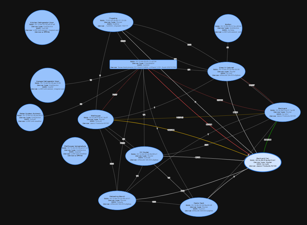
I digress somewhat. The Zigbee network as it stands today looks like this:

The mapping is automatically generated, though I did drag a few things around to make them fit the image a little better and to associate things somewhat physically.

There is, to me, an irritating feature of the map called Physics, which makes things move around on their own. It seems to seek to make the space between objects equal and consistent. It also seems to take off and do that just when I was reading something in the fine print on an object πŸ™‚ Happily, there is a checkbox to turn it off.

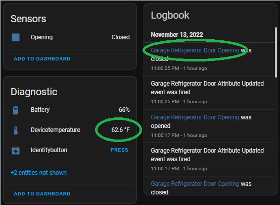
The rectangle is the controller. Ovals are router devices, circles are battery devices. At the upper left is the Kitchen Refrigerator door, which for some reason shows offline in this map just now, but it is definitely working. Maybe an auto mapping anomaly. Shrug. More importantly, you can see the aforementioned complexity of the meshing that Zigbee builds between routers.

The color coding seems to be related to signal strength, red low, yellow lowish, & green great. Most links, however, show gray and numbers lower than red, which is mildly confusing, but generally those devices are working.

I was hoping that the battery units would form more than one path to the controller, but maybe I don’t understand the way they work just yet.

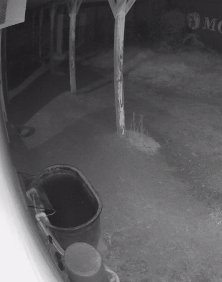
You may also note that I have a temperature sensor in the wellhouse. The wellhouse is a tiny metal building and even though the wellhouse plug router is only about 10 feet away, this temperature sensor does not work reliably at all. That may not be critical, but I do intend to automate based on the temperature *inside* the wellhouse, not just the the temperature outside. I will figure out something πŸ™‚

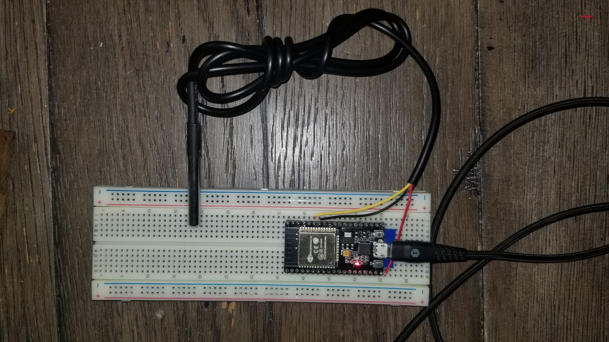
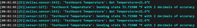
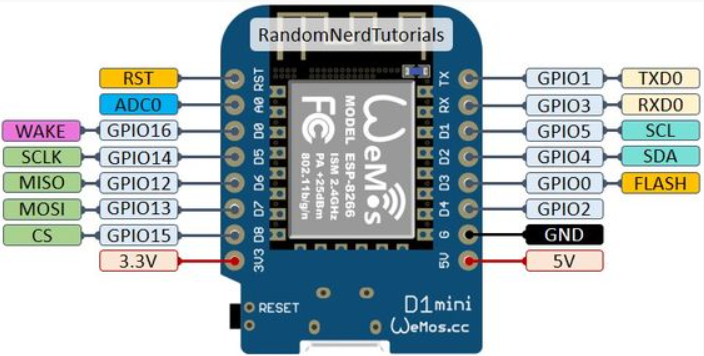
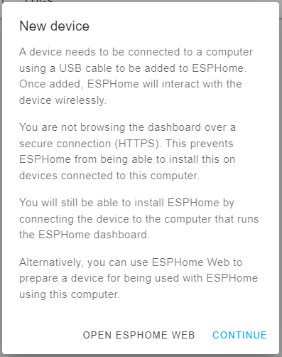
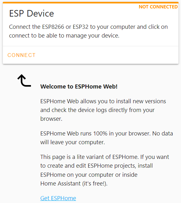
Up next, the very exciting world of ESPHome and I promise, the story about the Z-Wave debacle that I brought on myself.

Decapping Integrated Circuits

TL;DR: I am hoping to fix a broken USB drive….

For purely scientific interest, I have been interested in chip decapping for a while. Decapping is slightly archaic because only the larger integrated circuits tend to be made with actual removable caps these days.

Instead, ICs are FAR more commonly cast into epoxy and often glass reinforced epoxy.

There are a couple of destructive ways to decap epoxy chips. Sometimes you can literal just break the package and expose all or part of the silicon die with all the interesting bits therein, but that is really random. You can also use pretty extreme heat to soften the epoxy enough to peel it off the die.

The most effective way, and one which leaves at least a chance that the chip may still operate is to use heated 70% nitric acid to *dissolve* the epoxy. This is really effective and pretty hazardous, so requires good preparation and a not insignificant list of supplies, not the least of which is the 70% nitric acid. As I am writing this, a couple of online sources sell it to individuals for about $50 for a 100ml bottle (a little less that 1/2 cup Imperial) plus a $40 HazMat fee from the shipper. You need borosilicate glass (Pyrex is a brand name of borosilicate glass) because nitric acid will react with regular soda class. There are a lot of YouTube videos on the subject. I may tackle it for scientific purposes in the future, whenever I feel like dropping a hundred bucks on a half cup of evil juice.

What brings this whole subject to light is that a) I have had a physically damaged USB drive for many years and b) I have seen a few videos lately where talented individuals have used a fiber laser to vaporize the epoxy off of an SD card to expose the factory test connections in order to recover data on that card.

Now, I don’t have a spiffy fiber laser, but I do have an xTool D1 that I have been using for a variety of cutting and engraving projects. Surprisingly, as of this writing, the laser does not have it’s own blog category. Must fix.

This USB drive was in a laptop that was dropped. Instantly, it stopped working correctly. It would kinda work, showing a drive letter in Windows, but every attempt to interact with it would produce either an error or a bunch of nothing. For example, drive E: is there, with zero bytes in use, zero bytes available, etc. The card does mount, but there appears to be a disconnect between the controller and the actual storage within the device.

So, disassembly revealed that under all that plastic was a single tiny module, completely potted in epoxy, with a visible crack across it’s width.

On the other side of this module is the 4 pin USB connector on what is pretty obviously a printed circuit board. I suspect the entire device is a small board with naked chip dies attached and the whole thing potted in epoxy. All the plastic physical packaging is just to position and protect this little module. I should mention that this is a PNY brand device and it’s been long enough that I don’t remember the capacity, but it’s likely a 16MB or maybe 32MB. It’s not big by today’s standards.

This device was dropped quite some time ago, maybe 2012 or so. I think if I ever gain access, I’ll be able to realistically time stamp it, but I’m jumping WAY ahead. During those intervening years, I have occasionally tried to access the data. Mostly, I have tried to reflex the crack enough to make contact with whatever conductors were broken by the crack, which is generally my assumption as to what is broken. Maybe the PC board cracked in the right place to deny power to the storage chips, but not the controller. I don’t recall the specific utilities I used, but at least two of them were able to verify that the controller was responding, but that it could not see the storage.

So, back to the xTool D1. My particular device is a 10W blue diode laser that will cut up to about 10mm thick plywood, but it’s much happier with thinner stuff than that. I have cut everything from copier paper to acrylic to EVA foam and, with a little experimentation with the speed and power settings, it has performed wonderfully.

I didn’t want to just blindly charge into attempting to cut away the epoxy in my lobotomized USB drive, so I found a known dead circuit board and started eroding the epoxy on a couple of it’s onboard chips. I happened to pick the dead wireless link device that I had replaced earlier this year.

I set the xTool to ‘fill’ a 11mm square and positioned the laser over the left-most chip shown in the picture above. I played with various speed and power settings until I had an idea how it would chew it away.

I am not sure if it is specifically ash or if the laser burns away everything except the glass reinforcement, but a pass or two of the laser leaves a gray/white layer and the laser seems to no longer have much affect. Maybe if I had more than 10 watts to work with, it would be simpler.

After chipping and scraping away some layers of epoxy off of that chip, I decided that I had nothing left to lose by starting with those settings and seeing how it did with the USB drive module.

For the first pass, of COURSE I didn’t have the chip lined up perfectly, so it left a millimeter or so of chip untouched on the righthand side. I readjusted and ran the fill again. I noticed that the material was less “reactive”, it tended to reflect blue light rather than glow with a bright white burning color. I removed the module and used the corner of a single edge razor blade to chip away the gray/white ash layer.

If I was very careful, I could remove fairly large chips of this ash material. After a couple of passes, it looked like this:

Note a few specifics… I think rectangle in the upper left may be a capacitor being exposed. I hope the laser does not damage it.

Next, edges of the crack seem to erode quicker, leaving a trough that follows the crack. This may be a localized thermal effect.

Finally, you can definitely detect the 0.05mm spacing I chose to fill in the pattern. My experiments with the old wireless system chips showed that the default 0.1mm spacing was pretty crude at this level, but it *was* twice as fast to run. πŸ™‚

I ran the pattern a few more times and exposed the mother lode:

A bundle of bond wires, apparently all broken by the crack in the module.

It is good news because I am now confident I have found the problem. It is bad news because instead of maybe one or two broken power traces on the PC board, I have (I think 29) broken wires that fit roughly into a 3mm space.

I am *planning* to attempt to use fine solder paste and rework gun heat to solder bridge between the broken ends, somehow *not* also bridging the tiny 0.01mm gap between wires. I may make an attempt first to see if it will work at the current depth I have burned away with the laser. If not, I will need to tweak some laser values and try it again….

Starlink Ethernet Adapter

It’s a $20 part that, arguably, we shouldn’t have to add to our system, but that’s the way they built it, so….

My ethernet adapter arrived today. Mechanically, it’s very simple. A cable and box that plugs in between the rectangular dishy and the “router”/power supply.

To properly use it, one must disable the Starlink router, which is kinda bogus, by going into the Starlink app on your phone and setting the wifi mode to “bypass”. This mode setting, once committed, is reversible only by a manual factory reset. Sigh. Great design, guys.

In any case, it pretty much works.

I got a new IP address. It is pretty much just as useless at the previous one, but at least it’s in a different subnet.

The new IP for WAN is 100.64.0.1. All indications are that probably all systems with a square dishy will get the same semi-bogus address. According to ARIN, it is a “block is used as Shared Address Space.” Digging deeper, this range is set aside for what is called Carrier Grade Network Address Translation, or CGNAT. It makes sense that Starlink would use such a NAT scheme. It does cause some slight problems with inbound stuff, like port forwarding.

It replaced a WiFi access point, which was wired to my LAN and was the only WiFi device connected to Starlink, depicted below as FlyingHippy SSD.

This functioned perfectly, but as my whole LAN is arguably over complicated already, any simplification has to help. Also, although the WiFi specs published for the BrosTrend device are full speed on the wireless side, 867Mbps on 5GHz WiFi or 300Mbps on 2.4GHz WiFi. For my use case, where Starlink is the only WiFi device connected to it, those wireless specifications mean little because the wired ethernet is 100Mbps.

Since Starlink can exceed 100Mbps (sadly, only occasionally in practice), it was considered a potential bottleneck.

Is the Write Speed the Right Speed?

I have been aware that SD cards, and particularly MicroSD cards, can have read and write speed limitations, however, I only recently have had two separate issues that turn out to have been due to slow write speeds.

Though I didn’t realize it at the time, write speed was likely the issue that caused some videos taken by my little DJI Mavic Mini to fail. I started it recording and flew around for a while. Later, the video was only about a minute long; I had definitely intended to record more than that. I now think the slow SD card write speed caused the high resolution video to simply overwhelm the card and the camera just shut off. I presume there was no notice, but I will look for some kind of on screen warning in the future.

I also had troubles with a recent astrophotography capture. I was getting 100 subs of 30 seconds each. The length of the capture doesn’t affect the size of the file, but when you are going to capture for nearly an hour, you don’t want to wait any longer between shots than necessary. Most DSLR cameras will capture to an internal buffer then write that image to the memory card between pictures. Generally, the write time of the camera is hidden from the user because we tend to take a picture or two then put the camera down while we wait for something else to take a picture of to come around. However, with astrophotograhy, you are taking dozens or even hundreds of long exposures in a row. In the example above, I had the camera set to pause for two seconds between exposures. That pause time accounts for nearly four minutes in the whole capture process. I noticed that a little while into the capture, the busy light was staying lit past the time for the for the next picture to take. Because the intervalometer just sends a 1 second signal to the camera and the camera was using it’s internal shutter timer, when this busy event would happen, the camera miss a shutter event, which would then allow it to catch up on the write process then sit idle while the 31 or so second wait on the intervalometer would time out. It would then capture 5 or 6 images before the write busy would add up enough for it to miss another shutter event. So, my 100 captures would have turned out to be 90 or so without intervention.

I changed the delay between shots on the intervalometer to 5 seconds instead of two. This helped it get to 10 or 12 shots before the camera was busy and missed a shutter event. I set it to 8 seconds for the remaining 40-50 shots, the busy light did not miss any more shots.

Had the 8 second delay been in place for the entire 100 shots, it would have added 14 minutes to the entire process. It’s not like that is a huge part of one’s life, but after you capture 100 lights, then you need to capture 30-50 darks at the same shutter speed and 30-50 flats. The flats will be at a shorter shutter speed, but that actually makes the write speed problem worse.

I found, not surprisingly, that a) the read and write speed on memory cards is rarely specified and b) when it is, write speed has a bigger affect on price than capacity. 64GB cards with 250MB/S write speed cost more than 128GB cards with 130MB/S write speed and c) anything slower than about 100MB/S will probably not show the spec and those will pretty much always be inexpensive.

To address both problems, I ordered four 64GB cards that specify 250MB/S read and 130MB/S write speed from B&H Photo.

By the time they had arrived, I found some somewhat questionable data that indicated that the write speed of the particular card I had used in both the DJI Mavic Mini and the EOS Rebel T6i probably has a write speed more along the line of 30MB/S. I found a simple disk benchmark program and tested the new and old cards.

The old card, as expected, was pretty slow:

The new card was much faster, exceeding the write spec, assuming they specify the best spec rather than the average:

No SD card does well with random reads and writes.

For perspective, here is the report on the 250G SSD in my laptop:

… and my Toshiba 2TB USB drive that I use for various archiving and backup tasks:

In practical terms, I set the camera to it’s fastest shutter time of 1/4000 second and set it to continuous shooting. Press and hold the shutter button, and with the new card, it takes 7 pictures at the max speed of 5 frames per second, then it slows down to about 1 per second. Release the shutter button and it takes about 5 seconds for the busy light to go out. With the old card, you still get the 7 shots buffered in the camera, but the catchup is more like 1shot every 2 seconds, then it takes nearly 10 seconds for the busy light to go out. This card should definitely be an improvement.

Star Tracking

Although it was not strictly necessary in order to use my star tracker, I found decoding it’s terminology handy for finally helping me understand what acension and declination are. As a long time low intensity astronomy geek, I am embarassed to admit that I never really pursued understanding those terms. As it turns out, they are not particularly complicated. Viewing all of space as the inside surface of an imaginary sphere, right acension is essentially longitude and declination is latitude. Right ascension refers to the ascension, or the point on the celestial equator that rises with any celestial object as seen from Earth’s equator, where the celestial equator intersects the horizon at a right angle. The origin of the numbers is a point defined by the location of the sun on the March equinox; that line is currently in the constellation of Pices, but due to Earth’s axial precession, it moves about 1 degree west over a 72 year span. Declination is an extension of the earth’s equator into the celestial sphere and declination does follow the earth’s tilt and it also slowly moves in response to Earth’s axial precession.

In order to take longer individual exposures, I bought a tracking mount. A tracking mount, most commonly called a star tracker, is a telescope mount with a motor drive in it. If you set up the unit such that it’s right acension axis is parallel to Earth’s rotation axis, then the motor drive can rotate the mount in sync with the apparent motion of the sky, allowing you to capture significantly longer individual exposures with no (or very very little) distortion of the stars. This axis is generally abreviated RA for right acension and pronounced as the letters R A. This axis also usually has a clutch to temporarily disconnect it from the motor drive for coarse positioning.

Connected to the driven right acension axis is the physical mounting for your camera and/or telescope. This is called the declination mount and is usually abreviated DEC and pronounced “deck”. This mount also usually has a clutch or other release to facilitate coarse positioning the telescope.

I chose the iOptron SkyGuider Pro. I happened to purchase mine from High Point Scientific and at time of purchase, it was $488 USD. I also got the companion ball mount for my camera. This is not the absolutely cheapest tracker I could find, but it’s definitely among the least expensive options available. It’s size and flexability are well suited to my interests.

The SkyGuider Pro can carry up to 5 kg (11 pounds) of load balanced, but up to 1.5 kg (3.3 pounds) unbalanced. This is perfect for mounting a DSLR with a pretty normal lens without the complications of adding the declination mounting bracket with the counterweight attached.

It is about as simple as one could hope to set up. I have thus far used it on a decent photography tripod, though I imagine I will upgrade to a more astronomy minded tripod. However, I have not detected any issues that could be blamed on the tripod. To a point, the heavier and more rigid the tripod, the better.

The SkyGuider Pro can be set to track in the Northern or Southern hemispheres. It has 4 tracking speeds. 1X is straight sidereal tracking for astronomy. 1/2X is apparently for tracking sky and horizon together, though I have not tried this out, so I’m not sure how half speed helps either of those views. It can also track the sun or moon, as they move at slightly different speeds compared to sidereal.

It has a built in polar alignment scope with a reticle to help with proper alignment. The reticle has details for northern or southern hemisphere use and there are several apps to determine exactly where in the reticle Polaris or Sigma Octantis needs to be placed, based on the time and date and your location on the planet.

Polaris and Sigma Octantis are not precisely on the rotational axis of the Earth, just close. The crosshair is the actual axis and, for the time and date in this example, Polaris would need to be placed at the position shown by the little green cross for the tracker to be aligned with the polar axis.

It has two more features that I have not yet needed, an HBX port to connect an external control panel and an ST-4 compatible port for an external guiding signal.

The external control panel gives a little more control over tracking speed and some other parameters. The same port can be connected to a PC via an RS232 serial adapter to provide similar features that way.

The ST-4 port allows any of several guide scope/camera combos that use internal image processing to correct the tracking rate for VERY accurate tracking, which allows even longer exposures or longer focal lengths, where a tracking error would be more apparent. I am intrigued, but at this point in the hobby, I am shooting really wide fields and such additional guidance is not yet necessary.

So, for all these words, the SkyGuider Pro can be polar aligned, then the camera attached and pointed at a target and the tracker can kinda be forgotten; it just works.

This image was made from 100 stacked 30 second exposures. Admitedly, it’s not an exciting picture. That night I had hoped to get a shot of the unimaginatively named C/2017 K2 (PanSTARRS) comet. It’s closest approach was to be the following night. However, there was also a super moon in the same region of sky and I could not find the comet due mostly to the moon’s glare. Without much of anything else to specifically capture, I pointed the camera generally where the comet was expected to be and let it run as a test. The really bright moon is why the lower left of the frame is kinda foggy. I can’t find the comet in there anywhere, but if you zoom in on the stars, they are all nice and round; no streaking or egg shaped stars with a star tracker and 30 second exposures.

There *may* be a little evidence of nebulae in the lower left corner, but it is so overwhelmed by the moonglow that I’m not at all sure that’s what it is. By stretching it extensively, you can see a little bit of the formless form that is a nebula. Maybe. I will definitely be trying for more when the sky is darker.

I did try using the lunar speed setting and tracked the moon perfectly. I did not, however, *focus* the moon perfectly, so the moon shots were not worth sharing.

In any case, though I have not utilized it as heavily as I should, I have been very pleased with the SkyGuider Pro tracker and I will be using it much more this summer, especially after a new thing arrives. πŸ˜‰

Bahtinov Mask

Short version: I used my laser engraver to cut a custom Bahtinov mask for a particular camera lens I have.

Ripping pretty much directly from WikiPedia, a Bahtinov mask consists of three separate grids, positioned and angled such that the grids produce three angledΒ diffractionΒ spikes at theΒ focal planeΒ of the instrument for each bright image element.

As the instrument’s focus is changed, the central spike appears to move from one side of the star to the other. In reality, all three spikes move, but the central spike moves in the opposite direction to the two spikes forming the “X”. Optimal focus is achieved when the middle spike is centered between the other two spikes.

It didn’t take much searching to find webpage where someone much more brilliant than me had created a Bahtinov mask generator. This site takes various parameters and outputs SVG code/file that will import directly into LightBurn to run my laser.

Sidenote: The links on the Bahtinov mask generator page lead to some other versions of the mask and discussions about them and their development. It is an interesting read, though much of it was about colimating the optics on larger telescopes, so a bit off topic for me. Still, interesting stuff.

The target lens is a (cheap) Opteka 500mm reflex lens. I did not even know about astrophotography when I bought it; I was hoping to catch some wildlife around the house. There are mixed reviews about it and it’s stablemates, but it’s still the longest lens I currently have. It is an EF full frame lens, so a crop factor of 1.6 makes it perform on my Canon Rebel T6 as if it was an 800mm.

The default mask parameters appear to be for a largish telescope, 8+ inches in diameter. The parameters for my lens were:

The “Outer Diameter” is actually the inner diameter of the ring at the front of the lens. The “Inner Diameter” is the outer diameter of the center mirror. Stem/Slit width is the ratio between the elements of the grid. 1:1 means the slits and stems are the same width. Checking the “3rd order spectrum” increases the size of the stems and slits and makes the most sense with really large masks. I left mine unchecked. The (typo’d) “Bartinov Factor” is used in the math somewhere to determine the size and thus number of stems and slits, or basically how fine the elements are. I chose 120 experimentally. It yielded stems and slits that were about as wide as my black acrylic is thick. This is a fine pattern that seems strong. “inW” and “outW” is the margin between the inner and outer diameters and the elements of the Bahtinov pattern. I originally chose 1mm, and that’s probably ok, but I think 2mm would mask a little stronger, more robust mask. Finally, “Rounding” determines whether the ends of the slits are cut square or rounded. I chose rounded. Click on “Draw Bahtinov Mask” and you get:

I downloaded the SVG file, opened it in Lightburn and then proceeded to experiment with cut speed and power.

I have a 10 watt laser, which is adequate for every task I have asked it to do thus far, though I do need to experiment a bit for best results, especially with cutting, as opposed to engraving. For this material, I eventually landed on 100% power and a cutting speed of 8mm per second, with 2 passes. About 70% of the cutouts could be removed with the least pressure and the rest didn’t take much more work. I think I may try again with 6-7 mm per second to see if I can make them all fall free.

Of course, the first one did not go perfectly.

When I started cutting these, I had my wooden surface under the laser. it has a grid of alignment markings on it to help align targets for things engraving. When the laser would cut through the acrylic, it was marring that grid surface. I had the acrylic suspended on wooden blocks about 1-1/2″ above the grid, so I grabbed a piece of waste stock and was going to slip it under the acrylic, but I bumped the block and it moved the acrylic. I decided to let it finish so I could still test removing the cut parts, but it was not a pretty piece.

Note the off center cut, with no margin at the top and the overlapping cuts on the right side. I put the proper honeycomb aluminum cutting surface under it for the final cut.

As eluded to in the parameters section above, I think I would prefer a heavier margin between the edges and the grid. If I have cause to recut this one, I will make that adjustment. Also, I presume this is an artifact of the kerf for the laser, but note that stem/slit width ratio is not 1:1, as the parameters would suggest. A future mask may need that adjusted as well.

In any case, here is the completed mask, cleaned up and in place. All I need now is a night to test it. Interestingly, it fits under the lens cap, so I have a place to store it when it is not in use.

Astrophotography

No, not that one.

We’ve all seen stunning images of deep space objects. It turns out that, at pretty basic levels, those pictures aren’t particularly hard to capture. It does take more than pointing the camera and clicking the shutter, though.

I don’t remember for sure which is was, but YouTube recommended one of Nico Carver’s videos and it captured my attention. It may have been this one.

And before I go on, let me brag on Nico Carver a bit. His videos are chock full of how-to information, not just “look what I did” like some of the other channels I found. His is not the only one, but it is largely my goto for learning how to do this stuff.

As the above video suggests, if you have a DSLR camera, you may have everything needed to capture possibly stunning pictures of deep sky astronomical objects.

Astrophotography is done in two main steps, capturing the image then postprocessing the image. If you don’t capture good data, no amount of postprocessing can’t bring out the details you hope to see. If you capture good data, you can always process it over and over until you are happy with it.

Capturing the image is really done by capturing a LOT of images then using post processing techniques and software to “stack” them. This accomplishes two important things. First, deep sky objects tend to be dim, often too dim to see with the naked eye. Taking many short exposures then “stacking” them gives you a composite exposure that is MUCH longer. Taking 300 exposures is not uncommon. If they are 20 second exposures, the final stacked image could represent as much as 6000 seconds or 100 minutes of exposure. Of course, it will take a little longer than 100 minutes to take that many 20 second exposures. More on that later.

The absolute minimum to capture data is a DSLR camera with a decent lens, a sturdy tripod, a remote shutter release and a reasonably dark sky. Just a couple of fairly inexpensive accessories will raise the ease and quality of your captures and help ensure success.

An intervalometer is basically a remote shutter release with a programmable timer built in. You can set it to hit the shutter button 300 times every 21 seconds, for example. This not only automates the picture taking but also keeps you from shaking the camera to hit the shutter button. Most intervalometers as of this writing range from $20-50 on Amazon.

Focusing on stars is more difficult than it seems and sharp focus is critical to successful astrophotography. One of the simplest focusing aids is a Bahtinov mask. A Bahtinov mask is a cleverly arranged grid of lines cut into basically a lens cap. It sets up a diffraction spikes and when those spikes are in the proper orientation, sharp focus is assured. Bahtinov masks are widely priced, $15-$50 depending on size. My favorite is the right size to kind of clip into the internal threads of a skylight filter, which can then be screwed onto the end of my lens when needed.

For my first night of astrophotography, I was armed with my Canon Rebel T6 camera, a 75-300mm zoom lens that came with it, a Koolehaoda tripod I had originally purchased for something else and an intervalometer. The Amazon link to the one I purchased goes to a simple remote shutter release, but the link above is a physically identical device, with a different brand name πŸ™‚

I also had a camp chair, a flashlight and easy access to beverages.

I did not have a Bahtinov mask at that time, but I did manage to get a reasonably good focus because Jupiter was very easy to find in my west southwest sky and bright enough to get a good focus on. However, my desired subject was the Andromeda galaxy to the northwest.

It took quite a while for me to find Andromeda. I used either of a couple of apps (Sky Map and Star Walk 2) but my own fairly myopic eyesight, even corrected, had trouble seeing Andromeda, which *can* be seen with the naked eye in a dark enough sky. I started taking 10 second exposures to see if the camera could see it. After about 4-5 tries, it finally showed up. Also, once I finally knew exactly where to look, I could just see one star that was fuzzy, especially with binoculars.

I was able to carefully zoom and recenter and zoom and recenter until I finally had as big an image of it was I was gonna get.

Picture saved with settings embedded.

That little fuzzy blob in the middle is Andromeda. I did not know or notice at the time that there is another farther galaxy in the same shot. I am pretty sure you can’t see it here. The overall picture seems a little underwhelming at this point.

One of the things to experiment with, especially that first night, was how long of an exposure I could get. With no tracking mount at the time, I had to balance the maximum length of exposure to get the most light versus minimum exposure without the stars smearing from the earth’s rotation. You can determine this experimentally by starting with a guess, maybe 3 seconds, take an exposure and zoom in with the camera viewer to see if the stars are round. If they are, go higher, maybe 6 seconds and look again. When the stars start becoming egg shaped, back off the exposure time a little and check again. Keep at it until you get the longest exposure you can without distorting the stars.

There are also ways to calculate the exposure and several web calculators can be found to determine the exposure scientifically. However, untracked exposures will always be pretty quick, so I’m not sure it’s worth the trouble when there are only a small number of options in the less than 5 second range and it’s really easy to determine experimentally.

For me, with my particular collection of gear that night, it was 3 seconds. I decided to take 100 exposures at 3 seconds each, resulting in 5 minutes of total exposure. I didn’t realize it at the time, but that would be enough to get an ok image, but not nearly enough for the detail I had hoped for.

An important part of the capture process is to capture additional specialized images to help the processing software to do a better job at stacking all your exposures and reducing noise in the final image.

For terminology purposes, exposures are often called “frames” in astrophotography. I have not found a satisfactory explanation, but I presume it is based on frames of photographic film predating digital capture. The research continues. The exposures of your target are most often called “light frames”, meaning a collection of the light from our target object, collectively called “lights” or “subs”, for sub-exposures.

The calibration process has you capturing a number of frames under certain conditions. “Dark” frames or darks, are exposures at the same camera settings (ISO, exposure time, etc), and ideally at the same general time, as your light frames, but of complete darkness. Opinions vary, but most sources seem to recommend 30-50 or as many as 100 darks. This is super easy to accomplish. When you have finished capturing your lights, use a lens cap and perhaps an additional opaque cover over that to ensure that no light gets into the camera, then set your gear up to take another 30-50 shots with the same camera settings that was used for the lights. These frames are to capture what the noise from the camera sensor should look like so that the stacking software can account for it. If you use PhotoShop or GIMP to stretch the contrast of these darks, you will find that they are not completely dark. They have little spikes of non-dark which represents the electrical noise introduced by the current conditions in the camera.

The next calibration is with the camera set to the same ISO as your lights, but with a flat white unfocused subject and the shutter speed adjusted to a proper exposure and these are called “flat” frames or flats. The stacking software uses these frames to account for anomalies like dust or scratches on the lens or vigneting, a tendanacy for some lenses to not illuminate the sensor evenly, leaving the corners darker than the center. Your camera probably has a histogram feature to help set exposure and using it it probably the most accurate way. Accomplishing these is pretty easy. One easy way is to point the camera straight up, put a white T-shirt taught enough to not be wrinkled over the end of the lens, then put an even white light over then T-shirt, such as an iPad or a white LED tracing pad. Adjust the exposure to a reasonable setting, according to the exposure meter on the camera. Take another 30-50 or as many as 100 flat frames.

Another set of calibration frames is called “bias” frames. Similar to darks, these are captured with no light coming into the camera, but instead, they are with the camera set to it’s highest shutter speed. This shows the software another type of noise, the base noise pattern from the sensor in the camera without the averaging that happens in a longer exposure. Take another 30-50 or as many as 100 bias frames.

Postprocessing is a two step process. The first can be somewhat automated, using software like Deep Sky Stacker. It is certainly not completely automated, but DSS does the heavy lifting. It takes your lights, darks, flats and bias frames and analyzes all the details. It will align the stars in your lights so that they all stack correctly, analyze the calibration files to help eliminate noise and other anomalies and finally stack all your exposures into one low noise output image with a composite exposure time of all the (valid) light frames.

The next step is to crop the target and “stretch” the contrast with a photo editor like Photoshop or GIMP. This is not a particular difficult step, but it is kinda fiddly. I will defer the reader to Nico Carver’s videos for more and better information about that.

While the focus was good, the total exposure was pretty short, so cropping really close was a disappointing image, so this larger field is more pleasing.

The next time, I got 300 exposures of 3 seconds each, resulting in 15 minutes of total exposure. I had an iOptron SkyGuider Pro mount by then, though I was not super familiar with it and did not lengthen the individual exposure times, though I really could have.

The postprocessed results were about the same. I think part of the issue was that I had not nailed the focus as well. However, there was more light to work with, so I got a closer crop.

For boring reasons, I did not get to do any more captures before this summer, nearly an entire year.

Argus Panoptes

Ok, Argus Panoptes may be a little over the top since I currently only have five cameras instead of 100.

In the time we have lived out here in our largely rural property, I have had a few network cameras. My first foray into IP cameras was with a pair of DLink DCS-932 cameras, which if you follow that link, you will learn as I did that I can now only find it on D-Link’s non-US websites.

This camera served me fairly well. Its a wifi camera that can utilize, but does not require, a “cloud” presence to work. It outputs in fairly decent for it’s time 640×480 VGA, had auto night vision and built in IR illumination. It worked by a built in web server and could operate with either an ActiveX or Java applet.

I had one in the barn overlooking the stalls and one by the front door.

I still have them and so far as I know, they still work. I might add them to the mix someday.

More recently, I had an issue with a FedEx delivery. I was expecting a shipment that required a signature. I left the gate open and put a sign on the door that I work from home and to please ring the bell. Long story short, they “made” three delivery “attempts” and were about to return my goods, having not once rang my doorbell. My desk is within site of the front door and the dogs would not have slept through a doorbell.

I had to call and get a bit nasty and even then, the driver was literally walking away from my door 10 seconds after ringing the bell.

We hates them. They used to be the premier delivery service, but now I generally prefer even USPS.

That whole experience encouraged me to get a doorbell camera.

As mentioned in other blog posts, I am not exactly the best guy to try to sell on The Cloud. I appreciate the concept and my company is quite dependent on cloud services, not the least of which is RingCentral telephones, which is my particular gig within the company.

What I like about the cloud is great; it lets you export high powered data processing and storage to what the cloud really is, just someone else’s servers.

What I hate about many cloud dependent devices is that without a fast and reliable internet connection, it’s completely worthless crap that gets between you and a physical thing that you bought and are holding in your hand.

Thus was the state of affairs at our house. Our DSL was mostly worthless. That is to say, it was better than dialup. My first foray into home automation was with a Nexia z-Wave controller. I discovered it’s absolute reliance on an internet connection only once I had it installed. It worked, but the delay was unworkable. The worst case scenario was my wife hearing something while I was working out of town and hitting the button to turn on the outside lights, which, thanks to crappy DSL, would promptly turn on 20-30 seconds later, if at all. That was not gonna work.

So, I discovered Vera, which has cloud features, which are good, but it does not depend on an internet connection to work. That whole thing is documented elsewhere.

Those last few paragraphs are just to explain that I will not install something as critical as a security camera that depends on a internet connection to even work. I’m looking at you, Ring.

My shopping lead me in pretty short order to the Amcrest AD110, available from Amazon. Of course.

The installation of the doorbell camera was neat. I ordered a wedge thingy with it that pointed it more directly into the fourier that is our front entry.

The first issue I faced is that the AD110 is powered from the doorbell circuit and it requires at least 16V. It took some failures and some Googling to resolve it. Our existing doorbell transformer was only 10V, so a quick trip to the hardware store for a replacement fixed that issue.

Eventually, things settled in just fine and the next really important delivery, via FedEx of course, went better. I can’t actually claim that the camera had anything to do with it. At least the $1400 guitar my wife won from Sweetwater didn’t go back three times before they let us have it. Plus, I have Toni on camera walking out the front door right past that huge box without seeing it….

Flushed with this success, I ordered a couple more Amcrest cameras, a surface mount and a bullet mount. Both are PoE powered and have SD card slots for local recording. The surface mount ended up looking at the driveway and the bullet is in the barn looking at horse stalls.

I had some 32GB SD cards laying around and, not surprisingly, it doesn’t take long to fill this card up, especially if you don’t want to trust all recording to be triggered by motion alarms. The camera has parameters for when to start recording over older material. 32GB worked out to about 3 days. Since 256GB is 8 times the storage of 32GB, you’d think you would get 24-ish days, but instead, it only showed about two weeks.

I noticed that the camera had an option to store to Network Attached Storage and I had been thinking of building or getting one anyway, so that was all the excuse I needed.

For all the advantages of building a NAS from a Raspberry Pi or repurposing a PC or laptop, et cetera, I have reached an age and station wherein I just don’t wanna mess with stuff like that. I expired my cutting edge tech card a couple of decades ago. I like cool tech, but I just want it to work. Consequently, I shopped and decided on what is probably quite literally the lowest spec NAS that Synology currently sells, a DS120j. It is a 1 bay unit with an ARM processor. The ARM processor is the brains in a cubic buttload of smartphones, though it is not the only one. They are what most techies would call “markably powerful, within their limitations.” Good, cheap, but not the best. In any case, my DS120j, as ordered, came with a 2TB drive.

I’ll have to give it to them, though, it was a flawlessly easy setup. The NAS and the drive came in separate packaging, so the hardest thing was installing the drive into the cabinet. It took, maybe, 5 minutes. They are designed to go together, after all.

Before I even had much chance to set up a shared folder for the cameras, I noticed that one of Synology’s many available apps for the NAS is called Surveillance Station and it is basically a Network Video Recorder that is just included with a Synology NAS. It has WAY more features than the cameras alone and it bundles all your various cameras into a single interface. One throat to choke, so to speak.

One of the coolest things the NAS can do is give me access to data and more specifically, viewing the cameras, from outside of the house. This can be done with either a cloud redirect service Synology maintains or with port forwarding done in my own router. The DSCam app on my phone lets me check in remotely at pretty much any time. Plus, I just added every MP3, OGG and Apple music file I could find to the audio hosting feature it can also do.

Between the cameras and all the other stuff I have running on my NAS, such as backing up home directories on our various PCs, I was not necessarily pushing the 2TB storage, but in looking to the future, I elected to upgrade the space to 6TB anyway.

Anyway, this is night and day views of my five current cameras, four different models of cameras by Amcrest.

That magic number five turns out to be kind of an issue.

I quickly discovered that Synology Surveillance Station requires a license for each camera attached to it. The DS120j (and all models, I think) comes with two included licenses. Out of the box, you can only attach two cameras. I’m not a big fan of the license model; if you own a thing, you shouldn’t need a note from your Mom saying it’s ok to use it. I understand it, however, and I can choose to not put cameras on Surveillance Station or I can choose to buy licenses. I elected to purchase a four-pack of licenses because I could easily foresee six cameras in my system.

My next discovery was that the DS120j is limited to five cameras. It turns out that Synology, wisely, limits the number of cameras a NAS can monitor based on the capabilities of the host device hardware. The number is buried in the specs somewhere, but each model Synology NAS has a maximum number of cameras it can handle and mine can handle five. Consequently, I bought six licenses, one of which is not doing me any good.

Upgrade options are plentiful, though. Even the arguably least effective but cheapest upgrade is to the DS118, another single bay NAS, but it has significantly more processing power and it is rated for 12 IP cameras, $180 on Amazon as I write this. A more sensible upgrade would be for a two-bay system, where I could put the old 2TB together with the 6TB or upgrade for even more storage. The DS218 will do 25 cameras and the DS220 will do 20, for $250 or $300 respectively. More cameras and $50 less makes more sense to me.

In practical terms, I have captured a variety events, some planned, some not.

The very first thing I caught with the doorbell camera, which was the first camera as well, was escaped horses. I was expecting another delivery, so when the motion alarm went off, I hurried to the door and nobody was there. I went out side to see if I could catch them and what I caught instead was our two horses in the driveway. πŸ™‚

We live in the country, so we have wildlife. A family of raccoons frequents our barn. I’ve caught them on occasion just going out there, so I did expect to see some in the barn camera and was not disappointed. I did find it disappointing that they consider my camera to be climbing hold, even after I tried to cover it with something very uncomfortable to step on. Note the old D-Link camera post. That has been removed since this pic was taken. It was yet another climbing aid.

I had purchased a camera to put by the gate, but had not yet deployed it, so I set it up temporarily in the barn walkway, pointed at a live trap.

I eventually decided I would want a permanent camera for outside the barn doors and finally deployed the gate camera at the gate.

The challenge was power. There is a gate opener out there with a small solar panel to charge it. Experience has shown that it is adequate for keeping the gate battery charged and I considered just connecting the camera to that battery. The opener pulls such a tiny bit of current unless the operators are actually moving the gate, but the last thing I want to do is have a camera pulling current 24/7 and run down the battery just in time to lock my wife in or out.

The gate camera has a USB power cord and I have ordered a 12V to USB adapter dongle to connect directly to a battery. Due to the nature of the USB power, I could feel reasonably confident it should draw 10W or less. The new solar panel is larger, a 25W panel, probably more than is needed. I also found a charge controller that has USB outputs, so I don’t even need the power dongle anymore. I already had a couple of battery boxes and elected to rob a lawn tractor battery from a mower and replace it later.

I mounted the camera, connected it to my Wi-Fi network and reconfigured it as needed.

The gate controller is other side of the board. Yeah, the fence needs painting. I painted the gate back in October, though πŸ™‚

The camera catches any delivery vehicle, trash pickup, our own comings and goings, etc. I have the motion detection set to catch motion directly in front of the mailbox and, due to the close angle, I can get an alarm when the gate itself opens or closes.

I was not surprised to find that the Wi-Fi signal from the gate to the house is ok, but not really solid. My intent was to deploy an old Belkin Wi-Fi extender from years past. I have seen it recently, but I could not find it. I presume it is in a box that I didn’t open. Instead of continuing the search, I ordered a BrosTrend AC1200 to extend the house WiFi into the garage, which is closer to the gate. This increased signal strength somewhat. I think better positioning of the extender to expose it more to the garage window would bring it up even more.

The last camera I have on the NAS for now is another of the same model as the gate camera, mounted outside the barn with a view of the water trough and stall doors.

Sharp eyes may notice a dove nesting in the rafter, behind the minutes digits (43) of clock display.

One reason I wanted a camera out there is just to monitor the water trough, largely because one of the horses has done mischief with the equipment. That is why there is a steel guard covering the float valve. With the camera in place, it didn’t take long to catch some hijinks.

As I suspected, it’s Bonk. While you can’t see it in this still view, there is a green plastic tub that normally covers the water circulating pump. He had knocked it off earlier, then picked it up and moved it closer to the trough. The splashing he’s doing above was enough to put a couple of inches of water in the bottom of that tub. I found it entertaining.

One funny side effect of the cameras switching to night mode and turning on their IR illumination is that one camera can see evidence of another. The driveway camera can see the gate camera so well that I thought I had left the floodlight feature activated, visible here as a bright slash at the top center.

In this one, the light spilling from the stall doors is actually the illuminator on the stall camera.

Sluggy Blogs All The Subjects